Infiniti Q45 (FY33). Manual - part 528
 

  Index      Infiniti     Infiniti Q45 (FY33) - service repair manual 2001 year


Search            copyright infringement  


Content   ..  526  527  528  529   ..


Infiniti Q45 (FY33). Manual - part 528


SRS237

2.

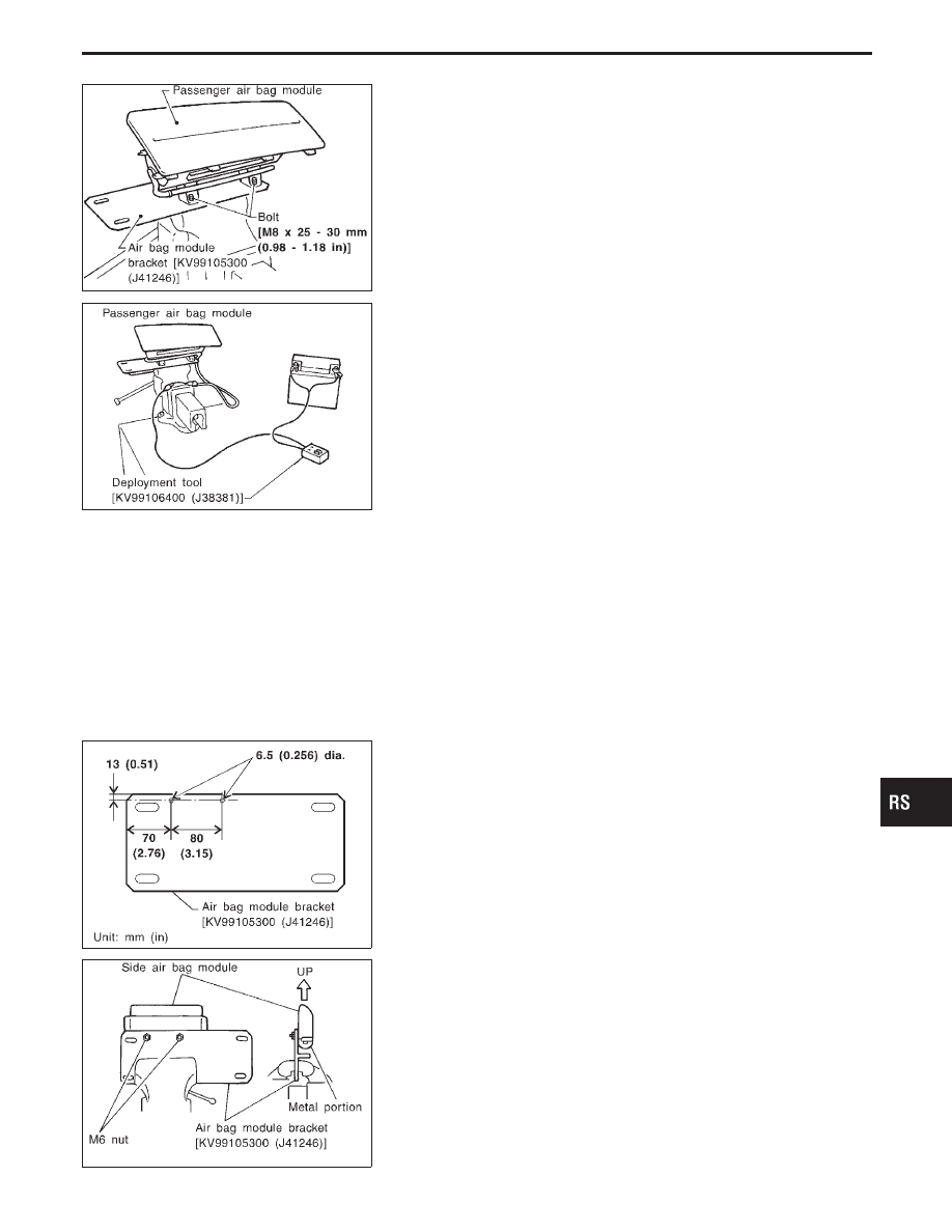
Firmly secure air bag module bracket [SST: KV99105300
(J41246)] in a vise.

3.

Match the two holes in air bag module bracket (held in vise)
and passenger air bag module and fix them with two bolts [M8
x 25 - 30 mm (0.98 - 1.18 in)].

CAUTION:

If a gap exists between passenger air bag module and air bag
module bracket, use a piece of wood inserted in the gap to
stabilize the air bag module.

SRS239

4.

Connect deployment tool adapter [SST: KV991065S0 (J38381-
30)] to deployment tool [SST: KV99106400 (J38381)] connec-
tor and connector of air bag module.

5.

Connect red clip of deployment tool to battery positive termi-
nal and black clip to negative terminal.

6.

The lamp on the right side of the tool, marked “deployment tool
power”, should glow green, not red.

7.

Press the button on the deployment tool. The left side lamp on
the tool, marked “air bag connector voltage”, will illuminate and
the air bag module will deploy.

CAUTION:

When deploying the air bag module, stand at least 5 m (16 ft)
away from the air bag module.

SRS490-A

Deployment of side air bag module (Built-in type)
(outside of vehicle)

1.

Make 6.5 mm (0.256 in) diameter holes in air bag module
bracket [SST: KV99105300 (J41246)] at the position shown in
figure at left.

SRS491-A

2.

Firmly secure air bag module bracket [SST: KV99105300
(J41246)] in a vise.

3.

Insert the stud bolts of side air bag module (built-in type) into
the two holes in air bag module bracket (held in vise) and fix
them with two M6 nuts.

CAUTION:

Side air bag module should be secured to air bag module
bracket [SST: KV99105300 (J41246)] in a vise with metal por-
tion facing down.

GI

MA

EM

LC

EC

FE

AT

PD

FA

RA

BR

ST

BT

HA

EL

IDX

SUPPLEMENTAL RESTRAINT SYSTEM (SRS)

Disposal of Air Bag Module and Seat Belt
Pre-tensioner (Cont’d)

RS-27

SRS020-B

4.

Connect deployment tool [SST: KV99106400 (J38381)] to side
air bag module connector.

5.

Connect red clip of deployment tool to battery positive termi-
nal and black clip to negative terminal.

6.

The lamp on the right side of the tool, marked “deployment tool
power”, should glow green, not red.

7.

Press the button on the deployment tool. The left side lamp on
the tool, marked “air bag connector voltage”, will illuminate and
the air bag module will deploy.

CAUTION:

When deploying the air bag module, stand at least 5 m (16 ft)
away from the air bag module.

SRS810

Deployment of seat belt pre-tensioner (outside of
vehicle)

1.

Firmly grip pre-tensioner in a vise and cut the webbing off.

SRS811

2.

Connect deployment tool adapter [SST: KV99108200 (J38381-
50)] to deployment tool [SST: KV99106400 (J38381)] connec-
tor and seat belt pre-tensioner connector.

SRS242

3.

Connect red clip of deployment tool to battery positive termi-
nal and black clip to negative terminal.

4.

The lamp on the right side of the tool, marked “deployment tool
power”, should glow green, not red.

5.

Press the button on the deployment tool. The left side lamp on
the tool, marked “seat belt pre-tensioner connector voltage”,
will illuminate and the seat belt pre-tensioner will deploy.

CAUTION:

When deploying the seat belt pre-tensioner, stand at least 5 m
(16 ft) away from the seat belt pre-tensioner.

SUPPLEMENTAL RESTRAINT SYSTEM (SRS)

Disposal of Air Bag Module and Seat Belt
Pre-tensioner (Cont’d)

RS-28

SRS006-A

DEPLOYMENT OF AIR BAG MODULE AND SEAT BELT
PRE-TENSIONER WHILE MOUNTED IN VEHICLE

When disposing of a vehicle, deploy air bag modules and seat belt
pre-tensioners while they are mounted in vehicle.

CAUTION:

When deploying air bag module or seat belt pre-tensioner,
ensure vehicle is empty.
1.

Disconnect both vehicle battery cables and wait 3 minutes.

2.

Disconnect air bag modules and seat belt pre-tensioners con-
nector.

3.

Connect deployment tool [SST: KV99106400 (J38381)] to air
bag module or seat belt pre-tensioner.
For front passenger air bag module, attach deployment tool
adapter [SST: KV991065S0 (J38381-30)] to the tool connector.
For seat belt pre-tensioner, attach deployment tool adapter
[SST: KV99108200 (J38381-50)] to the tool connector.

4.

Connect red clip of deployment tool to battery positive termi-
nal and black clip to negative terminal.

5.

The lamp on the right side of the tool, marked “deployment tool
power”, should glow green, not red.

6.

Press the button on the deployment tool. The left side lamp on
the tool, marked “air bag connector voltage”, will illuminate and
the air bag module or seat belt pre-tensioner will deploy.

CAUTION:

Activate only one air bag module or seat belt pre-tensioner at
a time.

SBF276H

DISPOSING OF AIR BAG MODULE AND SEAT BELT
PRE-TENSIONER

Deployed air bag modules and seat belt pre-tensioners are very
hot. Before disposing of air bag module, and seat belt pre-
tensioner, wait at least 30 minutes, and 10 minutes, respectively.
Seal them in a plastic bag before disposal.

CAUTION:

I

Never apply water to a deployed air bag module and seat
belt pre-tensioner.

I

Be sure to wear gloves when handling a deployed air bag
module and seat belt pre-tensioner.

I

No poisonous gas is produced upon air bag module
deployment. However, be careful not to inhale gas since it
irritates throat and can cause choking.

I

Do not attempt to disassemble air bag module and seat
belt pre-tensioner.

I

Air bag module and seat belt pre-tensioner cannot be re-
used.

I

Wash your hands clean after finishing work.

GI

MA

EM

LC

EC

FE

AT

PD

FA

RA

BR

ST

BT

HA

EL

IDX

SUPPLEMENTAL RESTRAINT SYSTEM (SRS)

Disposal of Air Bag Module and Seat Belt
Pre-tensioner (Cont’d)

RS-29

Trouble Diagnoses Introduction

CAUTION:

I

Do not use electrical test equipment to check SRS harness connectors unless instructed to in this
Service Manual. Spiral cable and wiring harnesses (except satellite sensor and side air bag mod-
ule) covered with yellow insulation tape either just before the harness connectors or for the com-
plete harness are related to the SRS.

I

Do not attempt to repair, splice or modify the SRS wiring harness. If the harness is damaged,
replace it with a new one.

I

Keep ground portion clean.

DIAGNOSIS FUNCTION

The SRS self-diagnosis results can be read by using “AIR BAG” warning lamp, “SEAT BELT” warning lamp
and/or CONSULT-II. The reading of these results is accomplished using one of two modes — “User mode”
and “Diagnosis mode”.
The User mode is exclusively prepared for the customer (driver). This mode warns the driver of a system
malfunction through the operation of the “AIR BAG” warning lamp and/or “SEAT BELT” warning lamp.
The Diagnosis mode allows the technician to locate and inspect the malfunctioning part.
The mode applications for the “AIR BAG” warning lamp, “SEAT BELT” warning lamp and CONSULT-II are as
follows:

User mode

Diagnosis mode

Display type

“AIR BAG” warning lamp

X

X

ON-OFF operation

“SEAT BELT” warning lamp

X

ON-OFF operation

CONSULT-II

X

Monitoring

DIAGNOSIS MODE FOR CONSULT-II

I

“SELF-DIAG [CURRENT]”
A current Self-diagnosis result (also indicated by the warning lamp flashes in the Diagnosis mode) is dis-
played on the CONSULT-II screen in real time. This refers to a malfunctioning part requiring repairs.

I

“SELF-DIAG [PAST]”
Diagnosis results previously stored in the memory (also indicated by the warning lamp flashes in the
Diagnosis mode) are displayed on the CONSULT-II screen. The stored results are not erased until memory
erasing is executed.

I

“TROUBLE DIAG RECORD”
With TROUBLE DIAG RECORD, diagnosis results previously erased by a reset operation can be displayed
on the CONSULT-II screen.

SRS752

I

“ECU DISCRIMINATED NO.”
The diagnosis sensor unit for each vehicle model is assigned
with its own, individual classification number. This number will
be displayed on the CONSULT-II screen, as shown at left.
When replacing the diagnosis sensor unit, refer to the part
number for the compatibility. After installation, replacement
with a correct unit can be checked by confirming this classifi-
cation number on the CONSULT-II screen.

For INFINITI Q45, the diagnosis sensor unit classification
number assigned is 2E.

TROUBLE DIAGNOSES — Supplemental Restraint System (SRS)

RS-30


Content   ..  526  527  528  529   ..