Infiniti I30 (A33). Manual - part 545
SLC240B
SLC926
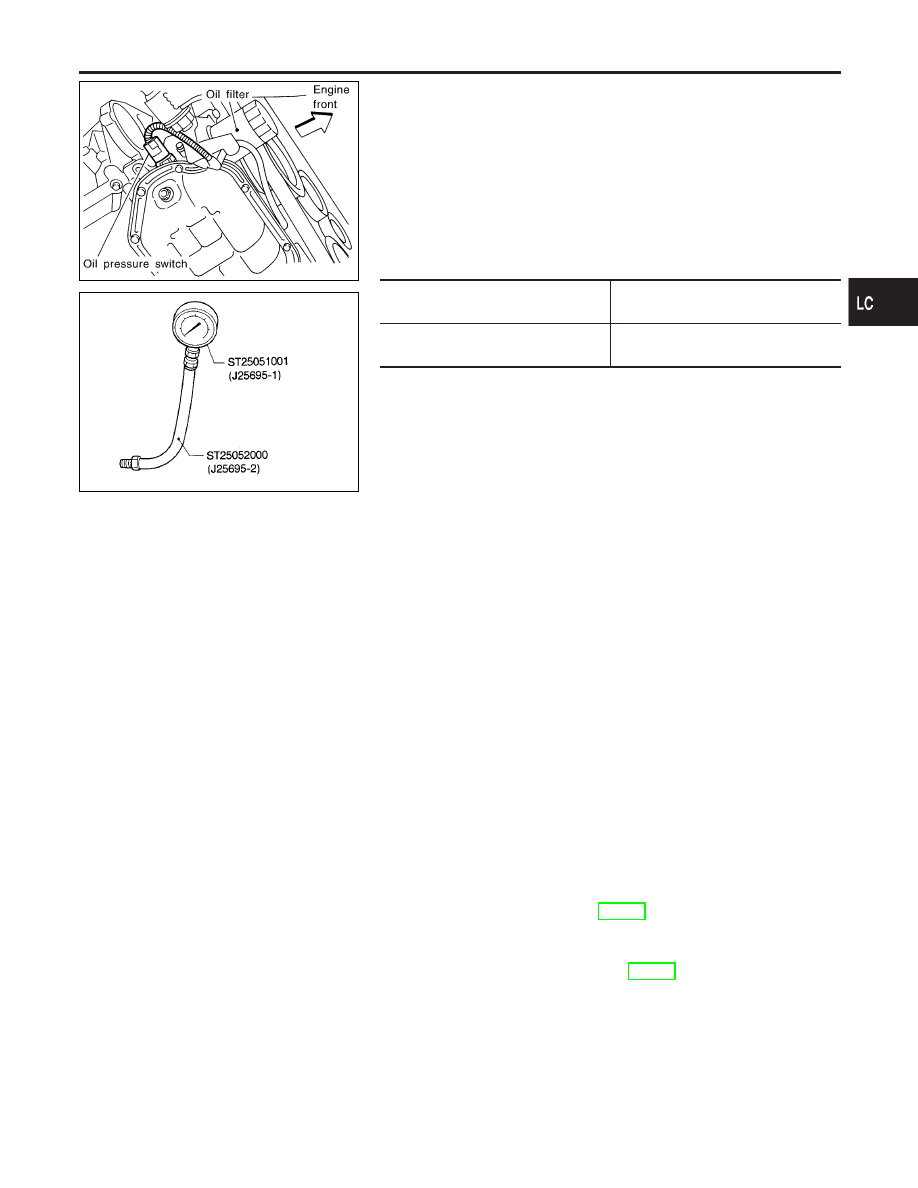
Oil Pressure Check
NHLC0004
WARNING:
I
Be careful not to burn yourself, as the engine and oil may
be hot.
I
Oil pressure check should be done in “Parking position”.
1.
Check oil level.
2.
Remove oil pressure switch.
3.
Install pressure gauge.
4.
Start engine and warm it up to normal operating temperature.
5.
Check oil pressure with engine running under no-load.
Engine speed
rpm
Approximate discharge pressure
kPa (kg/cm
2
, psi)
Idle speed
2,000
More than 98 (1.0, 14)
390 (3.98, 56.6)
If difference is extreme, check oil passage and oil pump
for oil leaks.
6.
Install oil pressure switch with sealant.
Oil Pump
REMOVAL AND INSTALLATION
NHLC0005
CAUTION:
When removing the oil pans, oil pump assembly and timing
chain from engine, first remove the camshaft position sensor
(PHASE) and the crankshaft position sensor (REF)/(POS) from
the assembly.
Be careful not to damage sensor edge.
1.
Drain engine oil.
2.
Remove drive belts.
3.
Remove camshaft position sensor (PHASE), and crankshaft
position sensor (REF)/(POS).
4.
Remove engine lower covers.
5.
Remove crankshaft pulley.
6.
Remove front exhaust tube and its support.
7.
Support engine at right and left side engine slingers with a
suitable hoist.
8.
Remove engine right side mounting insulator and bracket bolts
and nuts.
9.
Remove center member assembly.
10. Remove air compressor assembly and bracket.
11. Remove oil pans. Refer to EM-13, “Removal”.
12. Remove water pump cover.
13. Remove front cover assembly.
14. Remove timing chain. Refer to EM-22, “Removal”.
15. Remove oil pump assembly.
16. Reinstall any parts removed in reverse order of removal.
GI
MA
EM
EC
FE
AT
AX
SU
BR
ST
RS
BT
HA
SC
EL
IDX
ENGINE LUBRICATION SYSTEM
Oil Pressure Check
LC-5