Infiniti I30 (A33). Manual - part 264
15
CHECK VACUUM HOSE
Check vacuum hoses for clogging or disconnection. Refer to “Vacuum Hose Drawing”, EC-26.
OK or NG
OK (With CONSULT-II)
©
GO TO 16.
OK (Without CONSULT-
II)
©
GO TO 17.
NG
©
Repair or reconnect the hose.
16
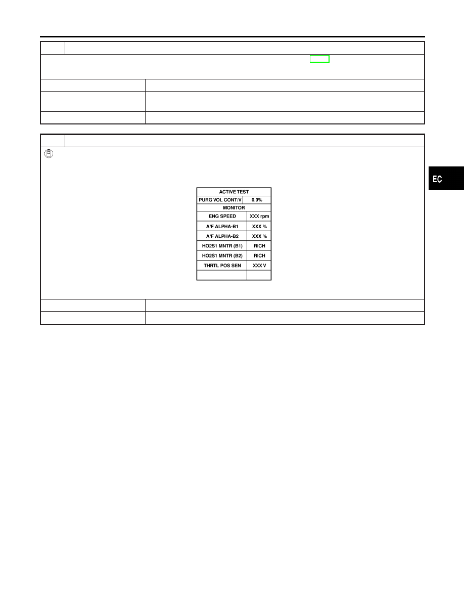
CHECK EVAP CANISTER PURGE VOLUME CONTROL SOLENOID VALVE
With CONSULT-II
1. Start engine.
2. Perform “PURG VOL CONT/V” in “ACTIVE TEST” mode with CONSULT-II. Check that engine speed varies according
to the valve opening.
SEF985Y
OK or NG
OK
©
GO TO 18.
NG
©
GO TO 17.
GI
MA
EM
LC
FE
AT
AX
SU
BR
ST
RS
BT
HA
SC
EL
IDX
DTC P0440 EVAP CONTROL SYSTEM (SMALL LEAK) (NEGATIVE PRESSURE)
Diagnostic Procedure (Cont’d)
EC-371