Infiniti I30 (A33). Manual - part 204
SEF242YA
GI
MA
EM
LC
FE
AT
AX
SU
BR
ST
RS
BT
HA
SC
EL
IDX
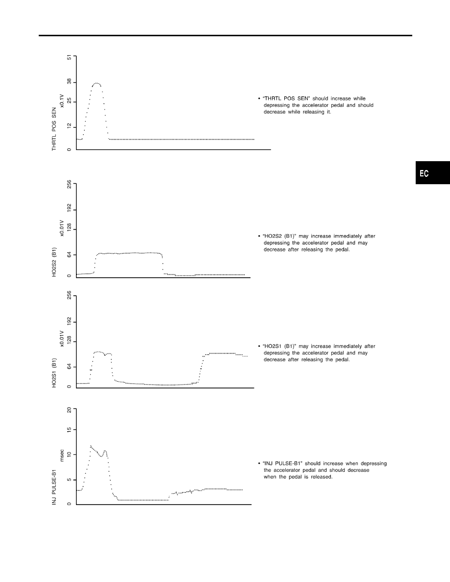
TROUBLE DIAGNOSIS — GENERAL DESCRIPTION
Major Sensor Reference Graph in Data Monitor Mode (Cont’d)
EC-131
|
|
|
SEF242YA GI MA EM LC FE AT AX SU BR ST RS BT HA SC EL IDX TROUBLE DIAGNOSIS — GENERAL DESCRIPTION Major Sensor Reference Graph in Data Monitor Mode (Cont’d) EC-131 |