Infiniti G35 (V35). Manual - part 781


  Index      Infiniti     Infiniti G35 (V35) Coupe - service repair manual 2007 year


Search            


Content   ..  779  780  781  782   ..


Infiniti G35 (V35). Manual - part 781


STC-28

[RAS]

TROUBLE DIAGNOSIS

2. 

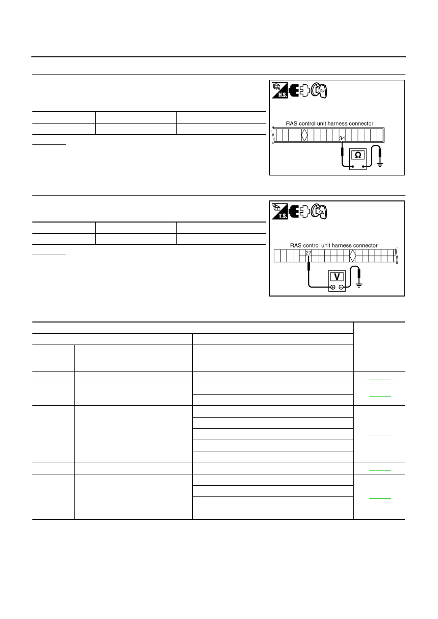
CHECK RAS CONTROL UNIT GROUND CIRCUIT

1.

Disconnect RAS control unit harness connector.

2.

Check continuity between RAS control unit harness connector
and ground.

OK or NG

OK

>> GO TO 3.

NG

>> Ground circuit open or shorted. Repair or replace any

inoperative parts.

3. 

CHECK RAS CONTROL UNIT POWER SUPPLY CIRCUIT

Turn ignition switch ON, and then check voltage between RAS con-
trol unit harness connector and ground.

OK or NG

OK

>> Power supply and ground circuit are normal.

NG

>> Power supply circuit open or shorted. Repair or replace

any inoperative parts.

Trouble Diagnosis Chart

NGS0009O

SELF-DIAGNOSIS

Connector

Terminal

Continuity

B136

34 

 Ground

Yes

SGIA1244E

Connector

Terminal

Voltage

B136

27 

 Ground

Battery voltage (Approx. 12 V)

SGIA1245E

Item

Reference

Self-diagnosis function

CONSULT-II

DTC

(warning 

lamp blinks)

Diagnosis item

Diagnosis item

11

Control unit

CONTROL UNIT [ABNORMAL 1 - 9]

STC-30

12

Motor power supply

MOTOR VOLTAGE [LOW VOLTAGE]

STC-30

MOTOR VOLTAGE [BAD OBSTRCT]

13

Motor output

MOTOR OUTPUT [ABNORMAL SIG]

STC-32

MOTOR OUTPUT [REV CURRENT]

MOTOR OUTPUT [NO CURRENT]

MOTOR OUTPUT [OVER CURRENT]

MOTOR OUTPUT [MOTOR LOCK]

21

Vehicle speed signal

VEHICLE SPEED SEN [NO SIGNAL]

STC-33

22

Steering angle signal

STEERING ANGLE SEN [NO CHANGE]

STC-33

STEERING ANGLE SEN [NO NEUT STATE]

STEERING ANGLE SEN [NO SIGNAL]

STEERING ANGLE SEN

TROUBLE DIAGNOSIS

STC-29

[RAS]

C

D

E

F

H

I

J

K

L

M

A

B

STC

DIAGNOSIS CHART BY SYMPTOM

24

Rear wheel steering angle (main)

RR ST ANGLE SENSOR [MAIN SIGNAL]

STC-35

RR ST ANGLE SENSOR [ABNORMAL VOL]

RR ST ANGLE SENSOR [OFFSET SIG1, 2]

25

Rear wheel steering angle (sub)

RR ST ANGLE SENSOR [SUB AIGNAL]

RR ST ANGLE SENSOR [ABNORMAL VOL]

RR ST ANGLE SENSOR [OFFSET SIG1, 2]

26

VDC

VDC

STC-37

27

Engine speed signal

MOTOR OUTPUT

STC-37

CAN COMM CIRCUIT [U1000]

STC-38

CONTROL UNIT (CAN) [U1010]

Symptom

Reference

It is not entering the self-diagnosis mode.

STC-27, "BASIC INSPECTION 3: RAS CONTROL UNIT POWER 
SUPPLY CIRCUIT AND GROUND CIRCUIT INSPECTION"

STC-39, "Inspection 10: Stop Lamp Switch Harness"

STC-39, "Inspection 11: RAS Warning Lamp Harness"

RAS warning lamp does not turn on with ignition switch ON.

STC-27, "BASIC INSPECTION 3: RAS CONTROL UNIT POWER 
SUPPLY CIRCUIT AND GROUND CIRCUIT INSPECTION"

STC-39, "Inspection 11: RAS Warning Lamp Harness"

RAS warning lamp turns on with ignition switch ON. It does 
not turn off even if the engine is started.

STC-27, "Basic Inspection"

STC-23, "Self-Diagnosis"

STC-26, "Diagnosis Procedure With Self-Diagnosis Function (With-
out CONSULT-II)"

RAS warning lamp may turn on after the engine is started.

STC-23, "Self-Diagnosis"

The steering force does not change smoothly according to 
the vehicle speed.

STC-41, "Diagnosis Chart by Symptom 2"

Noise

STC-23, "Self-Diagnosis"

STC-26, "Diagnosis Procedure With Self-Diagnosis Function (With-
out CONSULT-II)"

STC-8, "INSPECTION AFTER DISASSEMBLY"

Malfunction other than above

STC-41, "Diagnosis Chart by Symptom 1"

STC-30

[RAS]

TROUBLE DIAGNOSIS

Inspection 1: RAS Control Unit Malfunction

NGS0009P

1. 

CHECK SELF-DIAGNOSIS RESULTS

Check self-diagnosis results.

With CONSULT-II

Without CONSULT-II

Is above displayed on self-diagnosis display?

YES

>> Replace RAS control unit. Perform self-diagnosis again after replacing.

NO

>> INSPECTION END

Inspection 2: Motor Power Supply System

NGS0009Q

1. 

CHECK RAS CONTROL UNIT CONNECTOR

1.

Turn ignition switch OFF, disconnect RAS control unit harness connector and motor connector, and check
terminal for deformation, disconnection, looseness, etc.

2.

Reconnect harness connector securely, and perform self-diagnosis.

With CONSULT-II

Without CONSULT-II

Is above displayed on self-diagnosis display?

YES

>> GO TO 2.

NO

>> Connector terminal connection is loose, damaged, open, or shorted. Repair or replace the termi-

nal.

2. 

CHECK RAS MOTOR RELAY BATTERY CIRCUIT

1.

Turn ignition switch OFF, and disconnect RAS motor relay har-
ness connector.

2.

Check voltage between RAS motor relay harness connector and
ground.

OK or NG

OK

>> GO TO 3.

NG

>> RAS motor relay power supply circuit open or shorted.

Repair or replace power supply circuit and fuse.

Self-diagnostic results

CONTROL UNIT [ABNORMAL1 - 9]

DTC (warning lamp blinks)

11

Self-diagnosis results

MOTOR VOLTAGE [LOW VOLTAGE]

MOTOR VOLTAGE [BAD OBSTRCT]

DTC (warning lamp blinks)

12

Connector

Terminal

Voltage

B139

 Ground

Battery voltage (Approx. 12 V)

SGIA1246E

TROUBLE DIAGNOSIS

STC-31

[RAS]

C

D

E

F

H

I

J

K

L

M

A

B

STC

3. 

CHECK RAS MOTOR RELAY HARNESS

1.

Disconnect RAS motor relay harness connector and RAS control unit harness connector.

2.

Check continuity between the following terminals.

RAS motor relay harness connector B139 terminal 5 and RAS
control unit harness connector B136 terminal 37.

RAS motor relay harness connector B139 terminal 1 and RAS
control unit harness connector B136 terminal 25.

RAS motor relay harness connector B139 terminal 2 and
ground.

OK or NG

OK

>> GO TO 4.

NG

>> RAS motor relay harness open or shorted. Repair or replace applicable malfunctioning harness.

4. 

CHECK RAS MOTOR RELAY RESISTANCE

Check the resistance between RAS motor relay connector.

OK or NG

OK

>> GO TO 5.

NG

>> RAS motor relay malfunction (replacement)

5. 

CHECK RAS CONTROL UNIT OUTPUT SIGNAL

1.

Connect RAS control unit harness connector and RAS motor
relay harness connector.

2.

Check voltage between RAS motor relay harness connector and
ground.

OK or NG

OK

>> Check RAS motor relay separately from other parts.

Refer to 

STC-44, "RAS MOTOR RELAY"

 .

NG

>> RAS control unit malfunction (replacement)

Continuity should exist.

SGIA1265E

Connector

Terminal

Resistance

B139

 2

Approx. 74 

SGIA1266E

Connector

Terminal

Condition

Voltage

B139

 Ground

Ignition switch ON

Battery voltage (Approx. 12 V)

Ignition switch OFF

Approx. 0 V

SGIA1267E


Content   ..  779  780  781  782   ..