Infiniti G35 (V35). Manual - part 720
SC-16
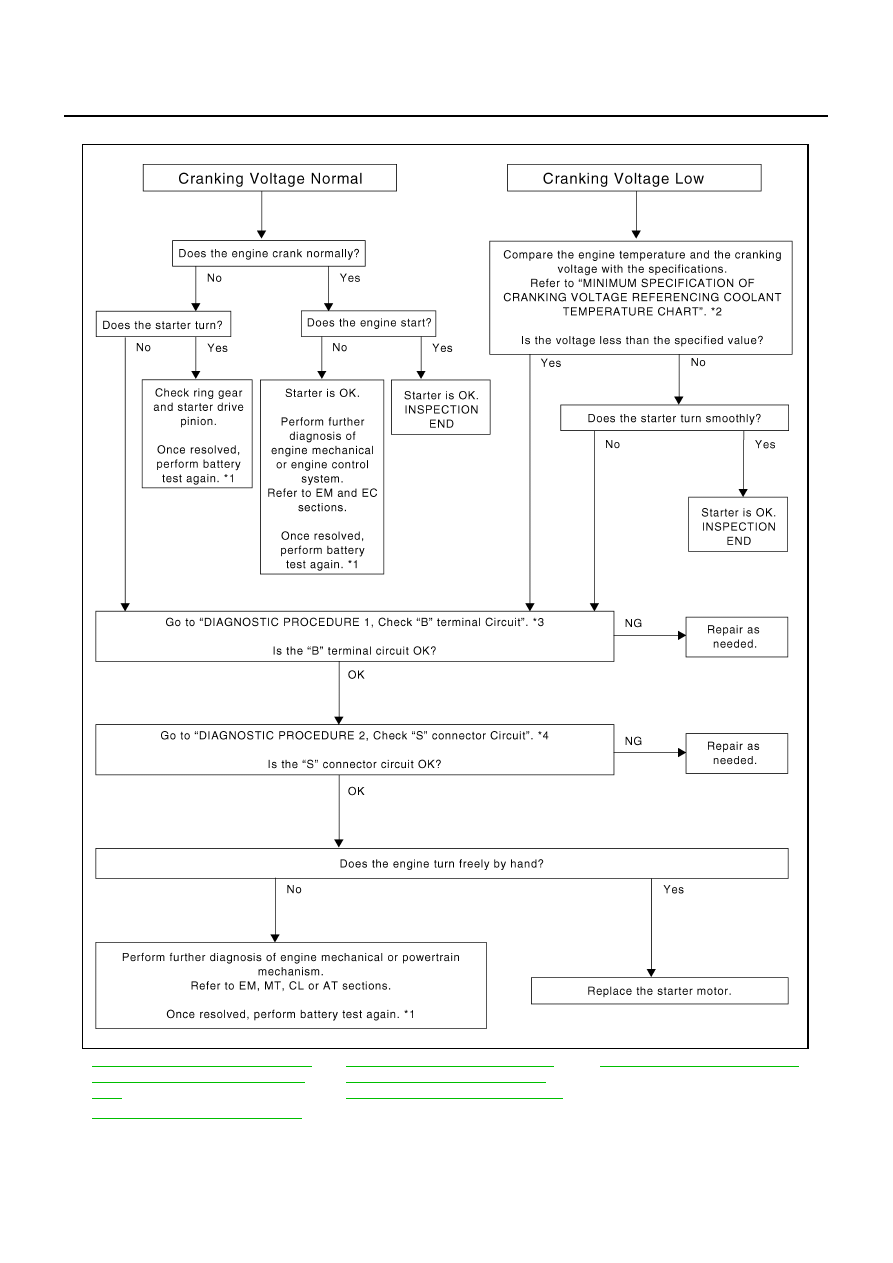
STARTING SYSTEM
WORK FLOW
SKIB1369E
*1
SC-6, "Trouble Diagnoses with Battery/
Starting/Charging System Tester (Bat-
tery)"
.
*2
SC-18, "MINIMUM SPECIFICATION
OF CRANKING VOLTAGE REFER-
ENCING COOLANT TEMPERATURE"
.
*3
SC-17, "Check “B” Terminal Circuit"
*4
SC-18, "Check “S” Connector Circuit"
.