Infiniti G35 (V35). Manual - part 678
PS-22
POWER STEERING GEAR
POWER STEERING GEAR
PFP:49001
Disassembly and Assembly
NGS000BH
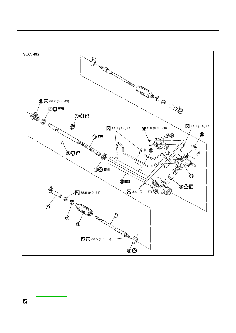
COMPONENTS
1.
Outer socket
2.
Boot clamp
3.
Boot
4.
Inner socket
5.
Boot clamp
6.
End cover assembly
7.
Rack oil seal
8.
Rack Teflon ring
9.
O-ring
10. Rack assembly
11.
Rack oil seal
12. Gear housing assembly
13. Cylinder tubes
14. Power steering solenoid valve
(with EPS)
15. O-ring
16. Gear sub-assembly
17. Rear cover cap
, and the followings for the symbols in the figure.
: Apply Genuine Thread Locking Sealant, Three Bound 1111B or equivalent.
SGIA1476E