Infiniti G35 (V35). Manual - part 546
 

  Index      Infiniti     Infiniti G35 (V35) Coupe - service repair manual 2007 year


Search            


Content   ..  544  545  546  547   ..


Infiniti G35 (V35). Manual - part 546


FRONT DOOR GLASS AND REGULATOR

GW-55

C

D

E

F

G

H

J

K

L

M

A

B

GW

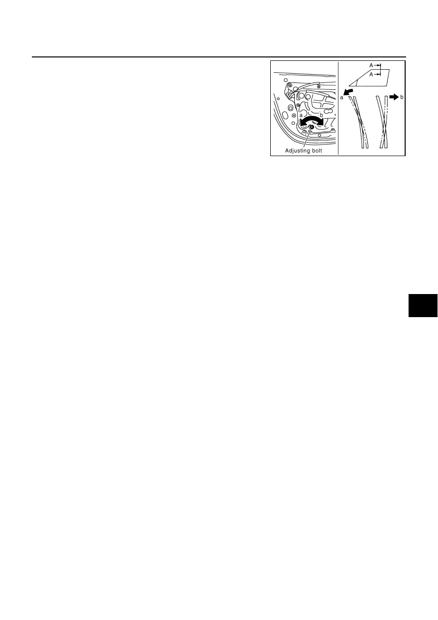
Raise the glass fully and adjust the glass top end and body side
welt fitting with the adjusting bolt at the lower of the regulator
rear rail.

NOTE:

Turn the adjusting bolt clockwise to move the door glass
upper end outward.

Turn the adjusting bolt counterclockwise to move the door
glass upper end inward.

PIIA7672E

GW-56

INSIDE MIRROR

INSIDE MIRROR

PFP:96321

Wiring Diagram –I/MIRR–

NIS000EY

TIWM1009E

INSIDE MIRROR

GW-57

C

D

E

F

G

H

J

K

L

M

A

B

GW

Removal and Installation

NIS000EZ

REMOVAL

1.

Remove the inside mirror finisher (if equipped).

2.

Disconnect the connector (if equipped).

3.

Remove the screw of mirror base.

4.

Slide the mirror upward to remove.

INSTALLATION

Install in the reverse order of removal.

CAUTION:

Apply Genuine Mirror Adhesive or equivalent to bonding surface of mounting bracket. Refer to 

GI-46,

"RECOMMENDED CHEMICAL PRODUCTS AND SEALANTS"

 .

1.

Inside mirror

2.

Inside mirror finisher (if equipped)

PIIA9845E

GW-58

REAR WINDOW DEFOGGER

REAR WINDOW DEFOGGER

PFP:25350

Component Parts and Harness Connector Location

NIS000F0

System Description

NIS000F1

The rear window defogger system is controlled by BCM (Body Control Module) and IPDM E/R (Intelligent
Power Distribution Module Engine Room). 
The rear window defogger  operates only for approximately 15 minutes. 
Power is at all times supplied

through 20A fuse [No. 75, and 80, located in the IPDM E/R] 

to rear window defogger relay terminal  3 and  6.

through 50A fusible link (letter F ,  located in the fusible link box)

to BCM terminal 55.

through 10A fuse [No. 18, located in the fuse block (J/B)]

to BCM terminal 42.

With the ignition switch turned to ON or START position, 
Power is supplied

through 10A fuse [No. 1, located in the fuse block (J/B)]

to BCM terminal 38.

through 10A fuse [No. 12, located in the fuse block (J/B)]

to rear window defogger relay terminal 1 and,

to A/C and audio controller terminal 2.

Ground is supplied

to BCM terminal 52

PIIB4035E


Content   ..  544  545  546  547   ..