Infiniti G35 (V35). Manual - part 347
 

  Index      Infiniti     Infiniti G35 (V35) Coupe - service repair manual 2007 year


Search            


Content   ..  345  346  347  348   ..


Infiniti G35 (V35). Manual - part 347


DTC P0132, P0152 A/F SENSOR 1

EC-269

C

D

E

F

G

H

I

J

K

L

M

A

EC

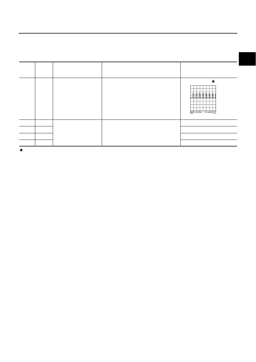
Specification data are reference values and are measured between each terminal and ground.
Pulse signal is measured by CONSULT-II.

CAUTION:

Do not use ECM ground terminals when measuring input/output voltage. Doing so may result in dam-
age to the ECM's transistor. Use a ground other than ECM terminals, such as the ground.

: Average voltage for pulse signal (Actual pulse signal can be confirmed by oscilloscope.)

TER-

MINAL 

NO.

WIRE 

COLOR

ITEM

CONDITION

DATA (DC Voltage)

2

OR

A/F sensor 1 heater
 (bank 1)

[Engine is running]

Warm-up condition

Idle speed

Approximately 5V

16

W

A/F sensor 1 (bank 1)

[Engine is running]

Warm-up condition

Idle speed

Approximately 3.1V

35

R

Approximately 2.6V

56

L

Approximately 2.3V

75

Y

Approximately 2.3V

PBIB1584E

EC-270

DTC P0132, P0152 A/F SENSOR 1

BANK 2

TBWM0824E

DTC P0132, P0152 A/F SENSOR 1

EC-271

C

D

E

F

G

H

I

J

K

L

M

A

EC

Specification data are reference values and are measured between each terminal and ground.
Pulse signal is measured by CONSULT-II.

CAUTION:

Do not use ECM ground terminals when measuring input/output voltage. Doing so may result in dam-
age to the ECM's transistor. Use a ground other than ECM terminals, such as the ground.

: Average voltage for pulse signal (Actual pulse signal can be confirmed by oscilloscope.)

Diagnostic Procedure

NBS000Y9

1. 

CHECK GROUND CONNECTIONS

1.

Turn ignition switch OFF.

2.

Loosen and retighten two ground screws on the body. Refer to 

EC-159, "Ground Inspection"

 .

OK or NG

OK

>> GO TO 2.

NG

>> Repair or replace ground connections.

TER-

MINAL 

NO.

WIRE 

COLOR

ITEM

CONDITION

DATA (DC Voltage)

24

OR

A/F sensor 1 heater 
(bank 2)

[Engine is running]

Warm-up condition

Idle speed

Approximately 5V

57

R

A/F sensor 1 (bank 2)

[Engine is running]

Warm-up condition

Idle speed

Approximately 2.6V

58

L

Approximately 2.3V

76

W

Approximately 3.1V

77

Y

Approximately 2.3V

PBIB1584E

PBIB2192E

EC-272

DTC P0132, P0152 A/F SENSOR 1

2. 

CHECK AIR FUEL RATIO (A/F) SENSOR 1 POWER SUPPLY CIRCUIT

1.

Disconnect air fuel ratio (A/F) sensor 1 harness connector.

2.

Turn ignition switch ON.

3.

Check voltage between A/F sensor 1 terminal 3 and ground with
CONSULT-II or tester.

OK or NG

OK

>> GO TO 4.

NG

>> GO TO 3.

3. 

DETECT MALFUNCTIONING PART

Check the following.

Harness connectors M72, F102

Harness connectors E108, M15

IPDM E/R harness connector E7

15A fuse

Harness for open or short between A/F sensor 1 and fuse

>> Repair or replace harness or connectors.

Voltage: Battery voltage

PBIB2100E

PBIB1683E


Content   ..  345  346  347  348   ..