Infiniti G35 (V35). Manual - part 277


  Index      Infiniti     Infiniti G35 (V35) Coupe - service repair manual 2007 year


Search            


Content   ..  275  276  277  278   ..


Infiniti G35 (V35). Manual - part 277


WARNING CHIME

DI-55

C

D

E

F

G

H

I

J

L

M

A

B

DI

3. 

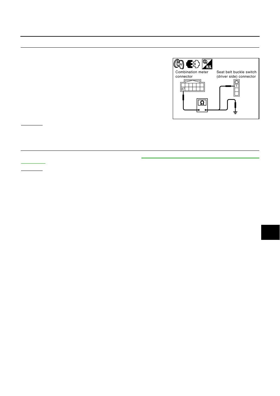
CHECK SEAT BELT BUCKLE SWITCH (DRIVER SIDE) CIRCUIT

1.

Turn ignition switch OFF.

2.

Disconnect combination meter connector and seat belt buckle
switch (driver side) connector.

3.

Check continuity between combination meter harness connector
M20 terminal 47 (BR) and seat belt buckle switch (driver side)
harness connector B8 terminal 1 (BR).

4.

Check continuity between combination meter harness connector
M20 terminal 1 (BR) and ground.

OK or NG

OK

>> GO TO 4.

NG

>> Repair harness or connector.

4. 

CHECK SEAT BELT BUCKLE SWITCH (DRIVER SIDE)

Check seat belt buckle switch (driver side). Refer to 

DI-54, "Seat Belt Buckle Switch (Driver Side) Signal

Inspection"

 .

OK or NG

OK

>> Check seat belt buckle switch (driver side) ground circuit.

NG

>> Replace seat belt buckle switch (driver side).

47 (BR) – 1 (BR)

: Continuity should exist.

47 (BR) – Ground

: Continuity should not exist.

SKIB4806E

DI-56

WARNING CHIME

Component Inspection

NKS000R5

DRIVER SIDE DOOR SWITCH

Check continuity between terminal 1 and door switch case ground.

KEY SWITCH

Check continuity between terminals 1 and 2.

KEY SWITCH AND IGNITION KNOB SWITCH

Check continuity between terminals 3 and 4.

SEAT BELT BUCKLE SWITCH (DRIVER SIDE)

Check continuity between terminals 1 and 2.

1 – Driver side door switch case ground

When driver side door 
switch is released

: Continuity should exist.

When driver side door 
switch is pushed

: Continuity should not exist.

SKIA7786E

1 – 2

When key is inserted to igni-
tion key cylinder

: Continuity should 
exist.

When key is removed from 
ignition key cylinder 

: Continuity should not 
exist.

SKIA5049E

3 – 4

When key is inserted to igni-
tion key cylinder

: Continuity should 
exist.

When key is removed from 
ignition key cylinder

: Continuity should not 
exist.

SKIA5060E

1 – 2

When seat belt (driver side) 
is fastened

: Continuity should not 
exist.

When seat belt (driver side) 
is unfastened

: Continuity should 
exist.

SKIB4802E

CAN COMMUNICATION

DI-57

C

D

E

F

G

H

I

J

L

M

A

B

DI

CAN COMMUNICATION

PFP:23710

System Description

NKS000R6

CAN (Controller Area Network) is a serial communication line for real time application. It is an on-vehicle mul-
tiplex communication line with high data communication speed and excellent error detection ability. Many elec-
tronic control units are equipped onto a vehicle, and each control unit shares information and links with other
control units during operation (not independent). In CAN communication, control units are connected with 2
communication lines (CAN H line, CAN L line) allowing a high rate of information transmission with less wiring.
Each control unit transmits/receives data but selectively reads required data only.

CAN Communication Unit

NKS000R7

Refer to 

DI-57, "CAN Communication Unit"

  in “LAN SYSTEM”.

DI-58

COMPASS

COMPASS

PFP:24835

System Description

NKS000KV

Display and A/C auto amp. displays earth magnetism and heading
direction of vehicle.

DIRECTION DISPLAY

Push the switch when the ignition switch is in the ON or START position. The direction will be displayed.

PKIB3823E


Content   ..  275  276  277  278   ..