Infiniti G35 (V35). Manual - part 165


  Index      Infiniti     Infiniti G35 (V35) Coupe - service repair manual 2007 year


Search            


Content   ..  163  164  165  166   ..


Infiniti G35 (V35). Manual - part 165


POWER DOOR LOCK SYSTEM

BL-47

C

D

E

F

G

H

J

K

L

M

A

B

BL

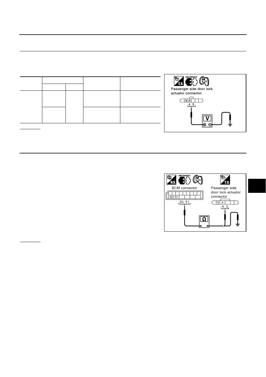
Check Passenger Side Door Lock Actuator 

NIS000BH

1. 

CHECK DOOR LOCK ACTUATOR SIGNAL

1.

Turn ignition switch OFF.

2.

Disconnect passenger side door lock actuator connector.

3.

Check voltage between passenger side door lock actuator connector D44 terminal 4, 5 and ground.

OK or NG

OK

>>  Replace passenger side door lock actuator.

NG

>> GO TO 2.

2. 

CHECK DOOR LOCK ACTUATOR  HARNESS

1.

Disconnect BCM and passenger side door lock actuator connector.

2.

Check continuity between BCM connector M2 terminals 50, 51 and passenger side door lock actuator
connector D44 terminals 4, 5 and ground. 

3.

Check continuity between BCM connector M2 terminals 50, 51
and ground.

OK or NG

OK

>> Replace BCM.

NG

>> Repair or replace harness.

Connector

Terminals (Wire color)

Condition

Voltage [V]

(Approx.)

(+)

(–)

D44

4 (PU)

Ground

Driver door lock/
unlock switch is 
turned to LOCK.

Battery 
voltage

 0

5 (L)

Driver door lock/
unlock switch is 
turned to UNLOCK.

Battery 
voltage

 0

PIIA3819E

50 (PU) – 4 (PU)

: Continuity should exist.

51 (W/L) – 5 (L)

: Continuity should exist.

50 (PU) – Ground

: Continuity should not exist.

51 (W/L) – Ground

: Continuity should not exist.

PIIA9544E

BL-48

POWER DOOR LOCK SYSTEM

Check Door Key Cylinder Switch 

NIS000BI

1. 

CHECK DOOR KEY CYLINDER SWITCH INPUT SIGNAL

 With CONSULT-II

Check door key cylinder switch (“KEY CYL LK-SW ” and “KEY CYL
UN-SW
 ”) in “DATA MONITOR” mode with CONSULT-II.

 Without CONSULT-II

Check voltage between power window main switch (door lock and
unlock switch) connector and ground.

OK or NG

OK

>> Replace power window main switch.

NG

>> GO TO 2.

2. 

CHECK DOOR KEY CYLINDER SWITCH CIRCUIT

1.

Turn ignition switch OFF.

2.

Disconnect power window main switch (door lock and unlock switch) and door key cylinder switch con-
nector.

3.

Check continuity between power window main switch (door lock and unlock switch) connector D7 terminal
6, 7 and door key cylinder switch connector D15 terminals 1, 6.

OK or NG

OK

>> GO TO 3.

NG

>> Repair or replace harness.

Door key cylinder switch is turned to lock

KEY CYL LK-SW

:ON

Door key cylinder switch is turned to unlock

KEY CYL UN-SW

:ON

PIIA4140E

Connector

Terminals (Wire color)

Key position 

Voltage [V] 

(Approx.)

(+)

(–)

D7

6 (Y)

Ground

Neutral/Unlock

5

Lock

0

7 (SB)

Neutral/Lock

5

Unlock

0

PIIA3352E

6 (Y) – 1 (Y)

:Continuity should exist.

7 (SB) – 6 (SB)

:Continuity should exist.

PIIA3816E

POWER DOOR LOCK SYSTEM

BL-49

C

D

E

F

G

H

J

K

L

M

A

B

BL

3. 

CHECK DOOR KEY CYLINDER SWITCH GROUND

Check continuity between door key cylinder switch connector D15 terminal 5 and ground.

OK or NG

OK

>> GO TO 4.

NG

>> Repair or replace harness.

4. 

CHECK DOOR KEY CYLINDER SWITCH

Check continuity between door key cylinder switch terminal 1, 6 and 5.

OK or NG

OK

>> Replace power window main switch.

NG

>> Replace door key cylinder switch.

Check Fuel Lid Lock Actuator 

NIS000BJ

1. 

CHECK FUEL LID LOCK ACTUATOR HARNESS

1.

Disconnect BCM and fuel lid lock actuator connector. 

2.

Check continuity between BCM connector M2 terminals 44, 50
and fuel lid lock actuator connector B418 terminals 1, 2.

3.

Check continuity between BCM connector M2 terminals 44, 50
and ground.

OK or NG

OK

>> Replace fuel lid actuator.

NG

>> Repair or replace harness.

5 (B) – Ground

: Continuity should exist.

PIIA3817E

Terminals

Key position

Continuity 

1

5

Neutral/Unlock

No

Lock

Yes

6

Neutral/Lock

No

Unlock

Yes

PIIA3818E

44 (Y) – 1 (L)

:Continuity should exist.

50 (PU) – 2 (PU)

:Continuity should exist.

44 (Y) – Ground

:Continuity should not exist.

50 (PU) – Ground

:Continuity should not exist.

PIIA9545E

BL-50

REMOTE KEYLESS ENTRY SYSTEM

REMOTE KEYLESS ENTRY SYSTEM

PFP:28596

Component Parts and Harness Connector Location

NIS000BK

1.

Horn relay E20

2.

Key switch connector M307 (View 
with steering column cover 
removed)

3.

BCM M1,M2,B4 (View with dash 
side LH removed)

4.

IPDM E/R E8,E9 (View with cowl top 
cover right removed)

5.

Remote keyless entry receiver M78 
(View with instrument lower passen-
ger panel removed)

6.

Driver side door switch B17 

7.

Trunk lid lock assembly (Trunk room 
lamp switch) B419

8.

a: Horn (Low) E32,E33
b: Horn (High) E35,E36

PIIB9057E


Content   ..  163  164  165  166   ..