Infiniti G35 (V35). Manual - part 158


  Index      Infiniti     Infiniti G35 (V35) Coupe - service repair manual 2007 year


Search            


Content   ..  156  157  158  159   ..


Infiniti G35 (V35). Manual - part 158


RADIATOR CORE SUPPORT

BL-19

C

D

E

F

G

H

J

K

L

M

A

B

BL

RADIATOR CORE SUPPORT

PFP:62500

Removal and Installation

NIS000B0

REMOVAL

1.

Remove hood assembly. Refer to 

BL-15, "Removal and Installation of Hood Assembly"

 .

2.

Remove front bumper, bumper reinforcement and bumper bracket. Refer to 

EI-14, "Removal and Installa-

tion"

 .

3.

Remove hood lock assembly, then remove hood lock cable.

4.

Remove washer tank. Refer to 

WW-37, "Removal and Installation of Washer Tank"

 .

5.

Remove horn connectors (High and Low).

6.

Remove the crash zone sensor. Refer to 

SRS-49, "Removal and Installation"

 .

7.

Disconnect the ambient sensor connector and remove the ambient sensor. Refer to 

ATC-115, "AMBIENT

SENSOR"

 .

8.

Remove mounting harness clip on radiator core support assembly, the harness is separate.

9.

Remove resonator mounting screws. Refer to 

EM-16, "AIR CLEANER AND AIR DUCT"

 .

10. Remove air duct (LH/RH), and remove washer tank inlet clip.

11. Remove the mounting bolts, and remove bumper bracket (LH/RH).
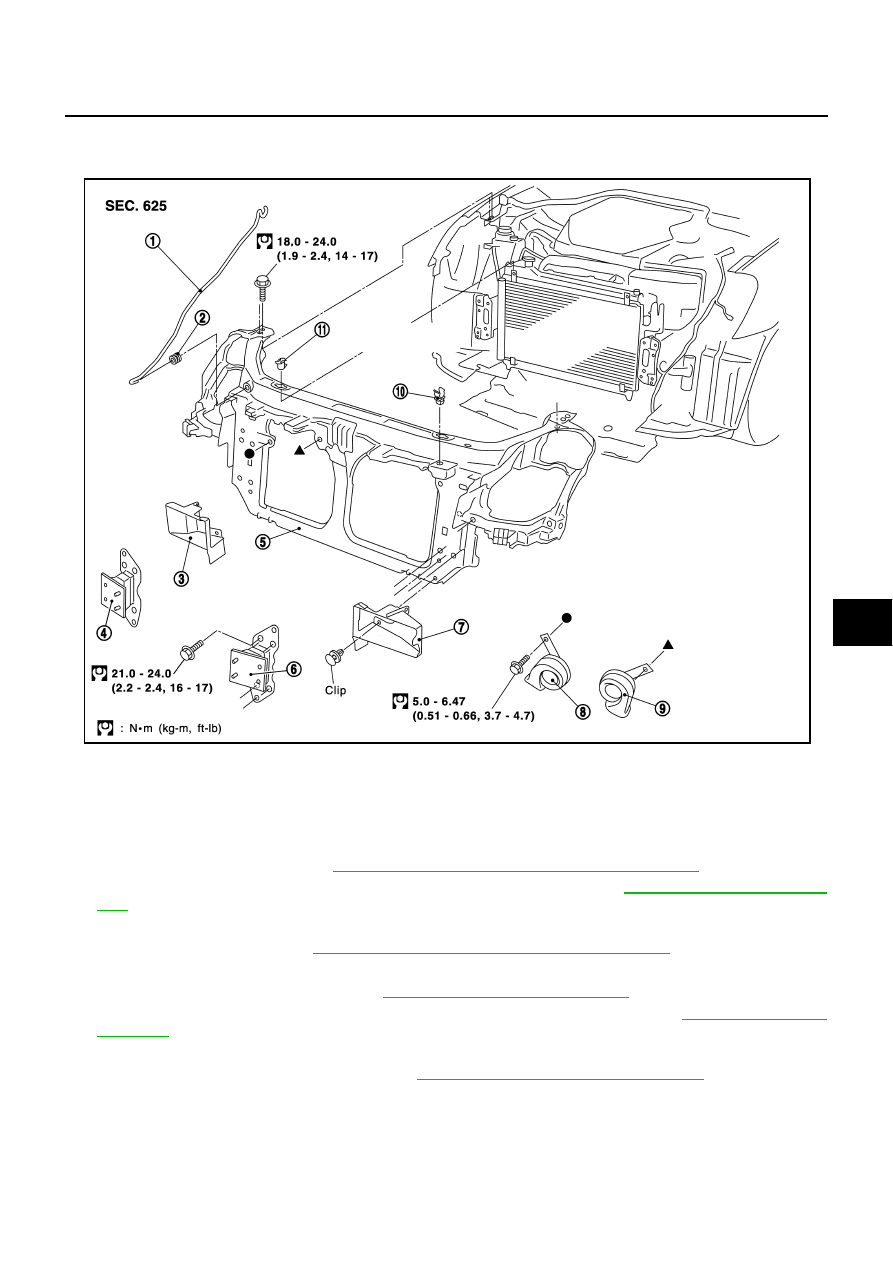
1.

Hood stay

2.

Grommet

3.

Air intake duct (RH)

4.

Bumper bracket (RH)

5.

Radiator core support assembly

6.

Bumper bracket (LH)

7.

Air intake duct (LH)

8.

Horn (High)

9.

Horn (Low)

10. Hood rod clamp

11.

Upper radiator bracket

PIIA3546E

BL-20

RADIATOR CORE SUPPORT

12. Remove upper radiator bracket, and radiator core support

assembly mounting bolts. Remove mounting bolts with power
tool

CAUTION:

Put a wooden block under the radiator assembly to prevent the
radiator assembly from falling.

13. Remove headlamp (LH/RH). Refer to 

LT-32, "Removal and

Installation"

 .

14. Remove radiator core support assembly.

15. After removing radiator core support assembly, the following

parts are separate.

Remove the hood stay, grommet and hood rod clamp

Horn (High/Low)

Air intake duct (LH/RH)

INSTALLATION

Installation in the reverse order of removal.

SIIA1150E

POWER DOOR LOCK SYSTEM

BL-21

C

D

E

F

G

H

J

K

L

M

A

B

BL

POWER DOOR LOCK SYSTEM

PFP:24814

Component Parts and Harness Connector Location

NIS000B1

*: With Intelligent Key

PIIB7423E

BL-22

POWER DOOR LOCK SYSTEM

System Description

NIS000B2

Power is supplied at all times

to BCM terminal 55

through 50A fusible link (letter F , located in the fuse and fusible link box).

to BCM terminal 42

through 10A fuse [No. 18, located in the fuse block (J/B)].

to key switch terminal 2

through 10A fuse [No. 21, located in the fuse block (J/B)].(without Intelligent Key)

to key and ignition knob switch terminals 1 and 3

through 15A fuse [No. 33, located in the fuse and fusible link box].(with Intelligent Key)

Ground is supplied at all times

to BCM terminal 52

through grounds M30 and M66.

When key switch is ON (key is inserted in ignition key cylinder), power is supplied

to BCM terminal 37

through key switch terminal 1. (Without Intelligent Key)

through key switch and ignition knob switch terminal 4. (With Intelligent Key)

When the driver side door switch is ON (door is OPEN), ground is supplied

to BCM terminal 62

through driver side door switch terminal 1 

through driver side door switch case ground.

When the passenger side door switch is ON (door is OPEN), ground is supplied

to BCM terminal 12

through passenger side door switch terminal 1 

through passenger side door switch case ground.

When the door is locked or unlocked with power window main switch (door lock and unlock switch),
 ground is supplied

to CPU of power window main switch

through power window main switch (door lock and unlock switch) terminal 15

through grounds M30 and M66.

Then power window main switch (door lock and unlock switch) operation signal is supplied

to BCM terminal 22

through power window main switch (door lock and unlock switch) terminal 12.

When the door is locked or unlocked with power window sub-switch (door lock and unlock switch), 
ground is supplied

to CPU of power window sub-switch

through power window sub-switch (door lock and unlock switch) terminal 11

through grounds M30 and M66.

Then power window sub-switch (door lock and unlock switch) operation signal is supplied

to BCM terminal 22

through power window sub-switch (door lock and unlock switch) terminal 16.

When the door is locked with door key cylinder switch, 
ground is supplied

to power window main switch (door lock and unlock switch) terminal 6

through door key cylinder switch terminals 1 and 5

through grounds M30 and M66.

Then door key cylinder switch operation signal is supplied

to BCM terminal 22

through power window main switch (door lock and unlock switch) terminal 12.


Content   ..  156  157  158  159   ..