Infiniti G35 (V35). Manual - part 97


  Index      Infiniti     Infiniti G35 (V35) Coupe - service repair manual 2007 year


Search            


Content   ..  95  96  97  98   ..


Infiniti G35 (V35). Manual - part 97


TROUBLE DIAGNOSIS

ATC-59

C

D

E

F

G

H

I

K

L

M

A

B

ATC

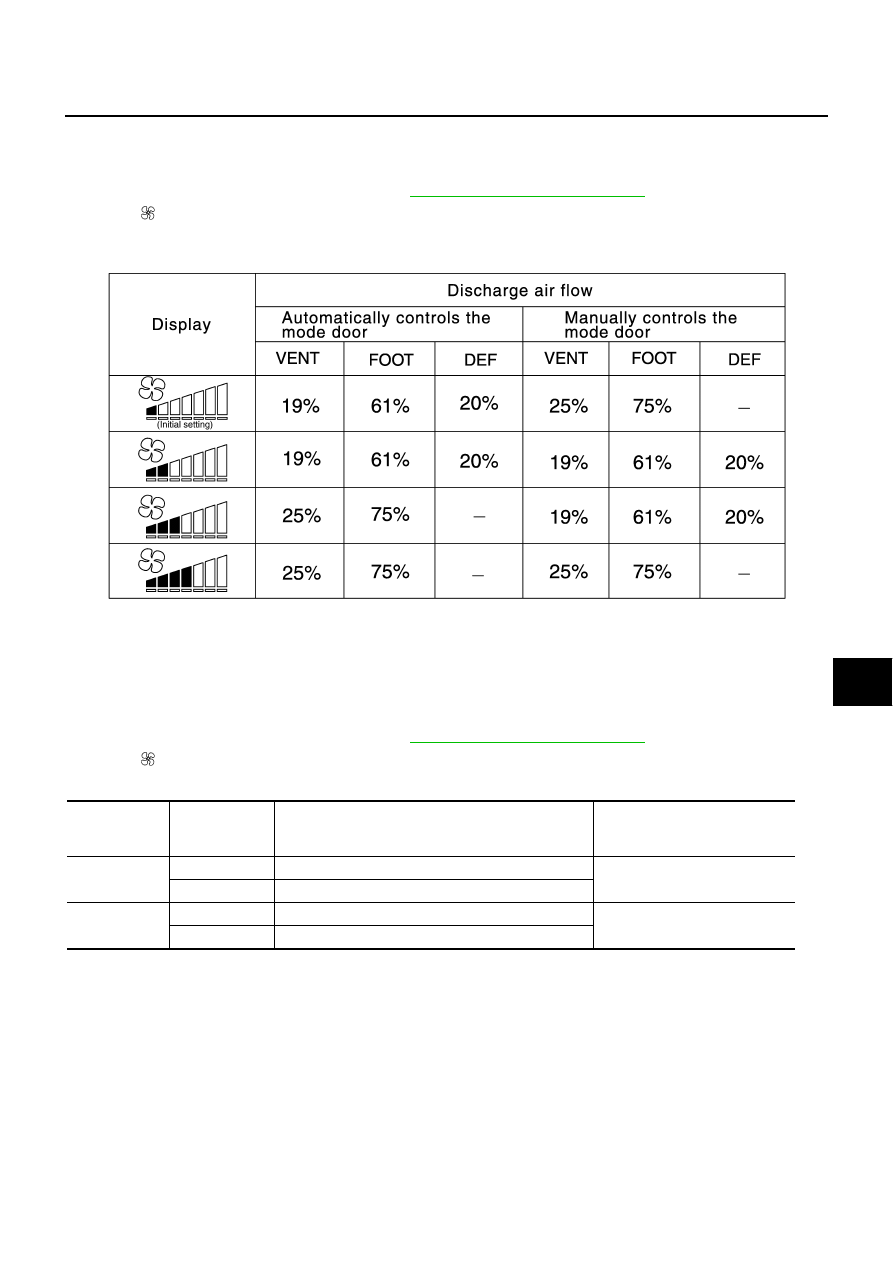
AUXILIARY MECHANISM: FOOT POSITION SETTING TRIMMER

Wind distribution ratio in FOOT mode can be set.
Operating procedures for this trimmer are as follows:
1.

Begin self-diagnosis STEP-5 mode. Refer to 

ATC-51, "Self-diagnosis Function"

 .

2.

Press   (fan) UP switch to set system in auxiliary mode.

3.

Display shows “61” in auxiliary mechanism. It takes approximately 3 seconds to enable setting operation.

4.

Press the mode switch as desired.

When battery cable is disconnected or battery voltage is below 10 V, trimmer operation is canceled. Wind dis-
tribution ratio set becomes that of initial condition.

AUXILIARY MECHANISM: INLET PORT MEMORY FUNCTION

When ignition switch is turned from OFF to ON, inlet port memory function at manual mode can be set.
Operating procedures for this trimmer are as follows:

1.

Begin self-diagnosis STEP-5 mode. Refer to 

ATC-51, "Self-diagnosis Function"

 .

2.

Press   (fan) UP switch to set system in auxiliary mode.

3.

Press the recirculation (REC) and fresh (FRE) switch as desired.

When battery cable is disconnected or battery voltage is below 10 V, memory function is canceled. Memory
function set becomes that of initial condition.

RJIA3487E

 Switch

LED status of 

REC/FRE 

switch

Setting status

Setting changeover method

REC

ON

Manual REC status is memorized. (Initial setting)

REC SW: ON

OFF

AUTO control

FRE

ON

Manual FRE status is memorized. 

FRE SW: ON

OFF

AUTO control (Initial setting)

ATC-60

TROUBLE DIAGNOSIS

Operational Check

NJS0003C

The purpose of the operational check is to check if the individual system operates properly.

CHECKING MEMORY FUNCTION

1.

Turn temperature control dial clockwise until  32

°

C (90

°

F) is displayed.

2.

Press OFF switch.

3.

Turn the ignition switch OFF.

4.

Turn the ignition switch ON.

5.

Press the AUTO.ECON switch.

6.

Confirm that the set temperature remains at previous temperature.

7.

Press OFF switch.

If NG, go to trouble diagnosis procedure for 

ATC-100, "Memory Function"

 .

If OK, continue the check.

CHECKING BLOWER

1.

Press fan switch (UP: +). Blower should operate on low speed. The fan symbol should have one blade lit.

2.

Press fan switch (UP: +), and continue checking blower speed and fan symbol until all speeds are
checked.

3.

Leave blower on max. speed. 

If NG, go to trouble diagnosis procedure for 

ATC-77, "Blower Motor Circuit"

 .

If OK, continue the check.

CHECKING DISCHARGE AIR

1.

Press MODE switch and DEF switch.

2.

Each position indicator should change shape.

3.

Confirm that discharge air comes out according to the air distri-
bution table. Refer to 

ATC-35, "Discharge Air Flow"

 .

Intake door position is checked in the next step.
If NG, go to trouble diagnosis procedure for 

ATC-68, "Mode Door

Motor Circuit"

 .

If OK, continue the check.

NOTE:
Confirm that the compressor clutch is engaged (sound or visual
inspection) and intake door position is at FRESH when D/F or DEF is
selected.

CHECKING INTAKE AIR

1.

Press recirculation (REC) switch. Recirculation indicator should illuminate.

2.

Press fresh (FRE) switch. Fresh indicator should illuminate.

3.

Listen for intake door position change. (Slight change of blower sound can be heard.)

If NG, go to trouble diagnosis procedure for 

ATC-74, "Intake Door Motor Circuit"

 .

If OK, continue the check.

CHECKING TEMPERATURE DECREASE

1.

Turn temperature control dial counterclockwise until 18

°

C (60

°

F) is displayed.

2.

Check for cold air at discharge air outlets.

If NG, go to trouble diagnosis procedure for 

ATC-89, "Insufficient Cooling"

 .

If OK, continue the check.

CHECKING TEMPERATURE INCREASE

1.

Turn temperature control dial clockwise until 32

°

C (90

°

F) is displayed.

2.

Check for hot air at discharge air outlets.

If NG, go to trouble diagnosis procedure for 

ATC-97, "Insufficient Heating"

 .

If OK, continue the check.

Conditions

: Engine running at normal operating temperature

SJIA0565E

TROUBLE DIAGNOSIS

ATC-61

C

D

E

F

G

H

I

K

L

M

A

B

ATC

CHECKING A/C SWITCH

1.

Press AUTO. ECON switch.

2.

Press A/C switch.

3.

A/C switch indicator will turn ON.

Confirm that the compressor clutch engages (sound or visual inspection).

If NG, go to trouble diagnosis procedure for 

ATC-82, "Magnet Clutch Circuit"

 .

If OK, continue the check.

CHECKING AUTO. ECON MODE

1.

Press AUTO. ECON switch.

2.

Display should indicate AUTO (not ECON).

3.

Press AUTO. ECON switch again.

4.

Display should indicate ECON.

Confirm that discharge air and blower speed will depend on ambient, in-vehicle, and set temperatures.

If NG, go to trouble diagnosis procedure for 

ATC-61, "Power Supply and Ground Circuit for Auto Amp."

 , then

if necessary, trouble diagnosis procedure for 

ATC-82, "Magnet Clutch Circuit"

 .

If all operational checks are OK (symptom cannot be duplicated), go to Incident Simulation Tests in 

GI-27,

"How to Perform Efficient Diagnosis for an Electrical Incident"

  and perform tests as outlined to simulate driv-

ing conditions environment. If symptom appears, refer to 

ATC-39, "SYMPTOM TABLE"

  and perform applica-

ble trouble diagnosis procedures.

Power Supply and Ground Circuit for Auto Amp.

NJS0003D

SYMPTOM: A/C system does not come on.

INSPECTION FLOW

*1

ATC-62, "DIAGNOSIS PROCE-
DURE FOR A/C SYSTEM"

*2

ATC-60, "Operational Check"

*3

ATC-111, "Multiplex Communication 
Circuit"

RJIA3496E

ATC-62

TROUBLE DIAGNOSIS

COMPONENT DESCRIPTION
Display and A/C Auto Amp. (Automatic Amplifier)

The display and A/C auto amp. has a built-in microcomputer which
processes information sent from various sensors needed for air con-
ditioner operation. The air mix door motor, mode door motor, intake
door motor, blower motor and compressor are then controlled.
When the various switches and temperature control dial are oper-
ated, data is input to the display and A/C auto amp. from the A/C and
audio controller using multiplex communication. 
Self-diagnosis functions are also built into display and A/C auto amp.
to provide quick check of malfunctions in the auto air conditioner
system.

Potentio Temperature Control (PTC)

The PTC is built into the A/C and audio controller. It can be set at an
interval of 0.5

°

C (1.0

°

F) in the 18

°

C (60

°

F) to 32

°

C (90

°

F) tempera-

ture range by turning temperature control dial. The set temperature
is displayed.

DIAGNOSIS PROCEDURE FOR A/C SYSTEM

SYMPTOM: A/C system does not come on.

RJIA3582E

RJIA3497E

RJIA3498E


Content   ..  95  96  97  98   ..