Infiniti G35 (V35). Manual - part 69


  Index      Infiniti     Infiniti G35 (V35) Coupe - service repair manual 2007 year


Search            


Content   ..  67  68  69  70   ..


Infiniti G35 (V35). Manual - part 69


DISASSEMBLY

AT-267

D

E

F

G

H

I

J

K

L

M

A

B

AT

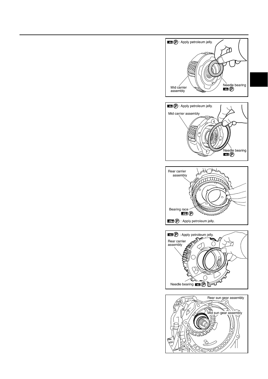
19. Remove needle bearing (front side) from mid carrier assembly.

20. Remove needle bearing (rear side) from mid carrier assembly.

21. Remove bearing race from rear carrier assembly.

22. Remove needle bearing from rear carrier assembly.

23. Remove mid sun gear assembly, rear sun gear assembly and

high and low reverse clutch hub as a unit.

CAUTION:

Be careful to remove then with bearing race and needle
bearing.

SCIA2805E

SCIA2804E

SCIA5175E

SCIA2803E

SCIA5018E

AT-268

DISASSEMBLY

24. Remove high and low reverse clutch assembly from direct clutch

assembly.

CAUTION:

Make sure that needle bearing is installed to the high and
low reverse clutch assembly edge surface.

25. Remove direct clutch assembly from reverse brake.

26. Remove needle bearing from drum support.

27. Remove snap ring from A/T assembly harness connector.

28. Push A/T assembly harness connector.

CAUTION:

Be careful not to damage connector.

SCIA2306E

SCIA5019E

SCIA5198E

SCIA5021E

SCIA5022E

DISASSEMBLY

AT-269

D

E

F

G

H

I

J

K

L

M

A

B

AT

29. Remove clips (1).

30. Remove oil pan (2) and oil pan gasket.

: Front

: Bolt (22)

Drain plug (3)

31. Check foreign materials in oil pan to help determine causes of

malfunction. If the ATF is very dark, smells burned, or contains
foreign particles, the frictional material (clutches, band) may
need replacement. A tacky film that will not wipe clean indicates
varnish build up. Varnish can cause valves, servo, and clutches
to stick and can inhibit pump pressure.

If frictional material is detected, perform A/T fluid cooler
cleaning. Refer to 

AT-14, "A/T Fluid Cooler Cleaning"

.

32. Remove magnets from oil pan.

33. Disconnect A/T fluid temperature sensor 2 connector (A).

CAUTION:

Be careful not to damage connector.

34. Straighten terminal clips to free terminal cord assembly and A/T

fluid temperature sensor 2 harness.

: Terminal clip (4)

35. Disconnect revolution sensor connector.

CAUTION:

Be careful not to damage connector.

SCIA8117E

SCIA5199E

SCIA5200E

SCIA8124E

SCIA7524E

AT-270

DISASSEMBLY

36. Straighten terminal clip to free revolution sensor harness.

37. Remove bolts A, B and C from control valve with TCM.

: Front

38. Remove control valve with TCM from transmission case.

CAUTION:

When removing, be careful with the manual valve notch and
manual plate height. Remove it vertically.

39. Remove A/T fluid temperature sensor 2 with bracket from con-

trol valve with TCM.

40. Remove bracket from A/T fluid temperature sensor 2.

SCIA7526E

Bolt symbol

Length mm (in)

Number of bolts

A

42 (1.65)

5

B

55 (2.17)

6

C

40 (1.57)

1

SCIA8077E

SCIA5260E

SCIA5301E

SCIA5264E


Content   ..  67  68  69  70   ..