Infiniti G35 (V35). Manual - part 9
A/T CONTROL SYSTEM
AT-27
D
E
F
G
H
I
J
K
L
M
A
B
AT
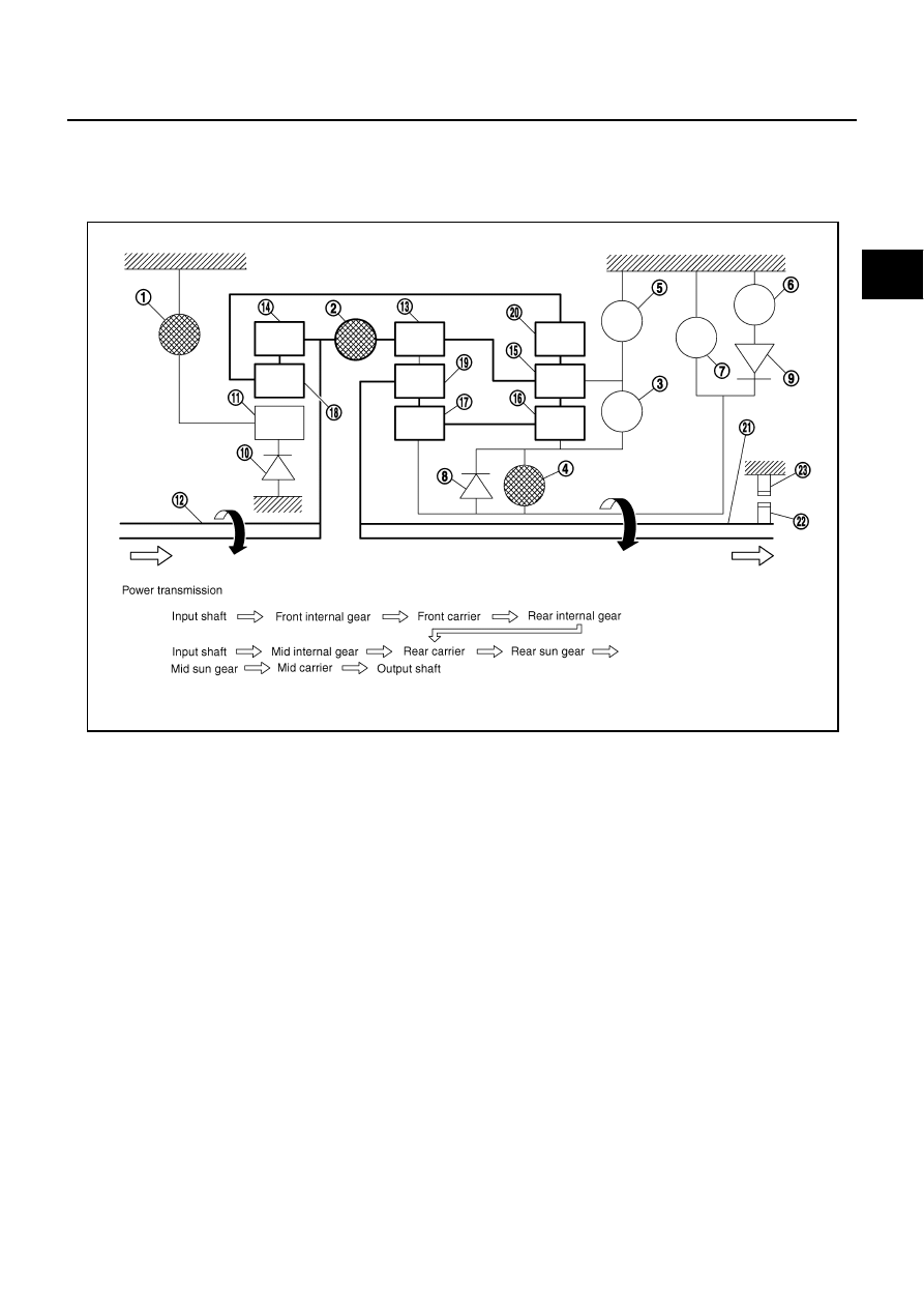
“D
5
” and “M5” Positions
●
The front brake fastens the front sun gear.
●
The input clutch is coupled, and the front internal gear and mid internal gear are connected.
●
The high and low reverse clutch is coupled, and the mid sun gear and rear sun gear are connected.
1.
Front brake
2.
Input clutch
3.
Direct clutch
4.
High and low reverse clutch
5.
Reverse brake
6.
Forward brake
7.
Low coast brake
8.
1st one-way clutch
9.
Forward one-way clutch
10. 3rd one-way clutch
11.
Front sun gear
12. Input shaft
13. Mid internal gear
14. Front internal gear
15. Rear carrier
16. Rear sun gear
17. Mid sun gear
18. Front carrier
19. Mid carrier
20. Rear internal gear
21. Output shaft
22. Parking gear
23. Parking pawl
SCIA4984E