Content .. 1829 1830 1831 1832 ..
Infiniti FX35, FX50 (S51). Manual - part 1831
SELECTOR LEVER POSITION INDICATOR
TM-131
< DTC/CIRCUIT DIAGNOSIS >
[7AT: RE7R01A (VQ35HR)]
C
E
F
G
H
I
J
K
L
M
A
B
TM
N
O
P
Is the inspection result normal?
YES
>> Check intermittent incident. Refer to
GI-36, "Intermittent Incident"
.
NO
>> Replace damaged parts.
8.
CHECK HARNESS BETWEEN A/T SHIFT SELECTOR AND BCM (PART 1)
1.
Turn ignition switch OFF.
2.
Disconnect BCM connector.
3.
Check continuity between A/T shift selector vehicle side harness connector terminal and BCM vehicle
side harness connector terminal.
Is the inspection result normal?
YES
>> GO TO 9.
NO
>> Repair or replace damaged parts.
9.
CHECK HARNESS BETWEEN A/T SHIFT SELECTOR AND BCM (PART 2)
Check continuity between A/T shift selector vehicle side harness connector terminal and ground.
Is the inspection result normal?
YES
>> GO TO 10.
NO
>> Repair or replace damaged parts.
10.
CHECK BCM INPUT/OUTPUT SIGNAL
Check BCM input/output signal. Refer to
.
Is the inspection result normal?
YES
>> Check intermittent incident. Refer to
GI-36, "Intermittent Incident"
.
NO
>> Repair or replace damaged parts.
11.
CHECK POWER SOURCE
1.
Turn ignition switch OFF.
2.
Disconnect A/T shift selector connector.
3.
Turn ignition switch ON.
4.
Check voltage between A/T shift selector vehicle side harness connector terminals.
Is the inspection result normal?
YES
>> GO TO 12.
NO
>> Check illumination circuit. Refer to
INL-89, "Wiring Diagram - ILLUMINATION -"
.
12.
CHECK SHIFT POSITION SWITCH
1.
Disconnect shift position switch connector.
2.
Check continuity between A/T shift selector harness connector terminals and shift position switch connec-
tor terminals.
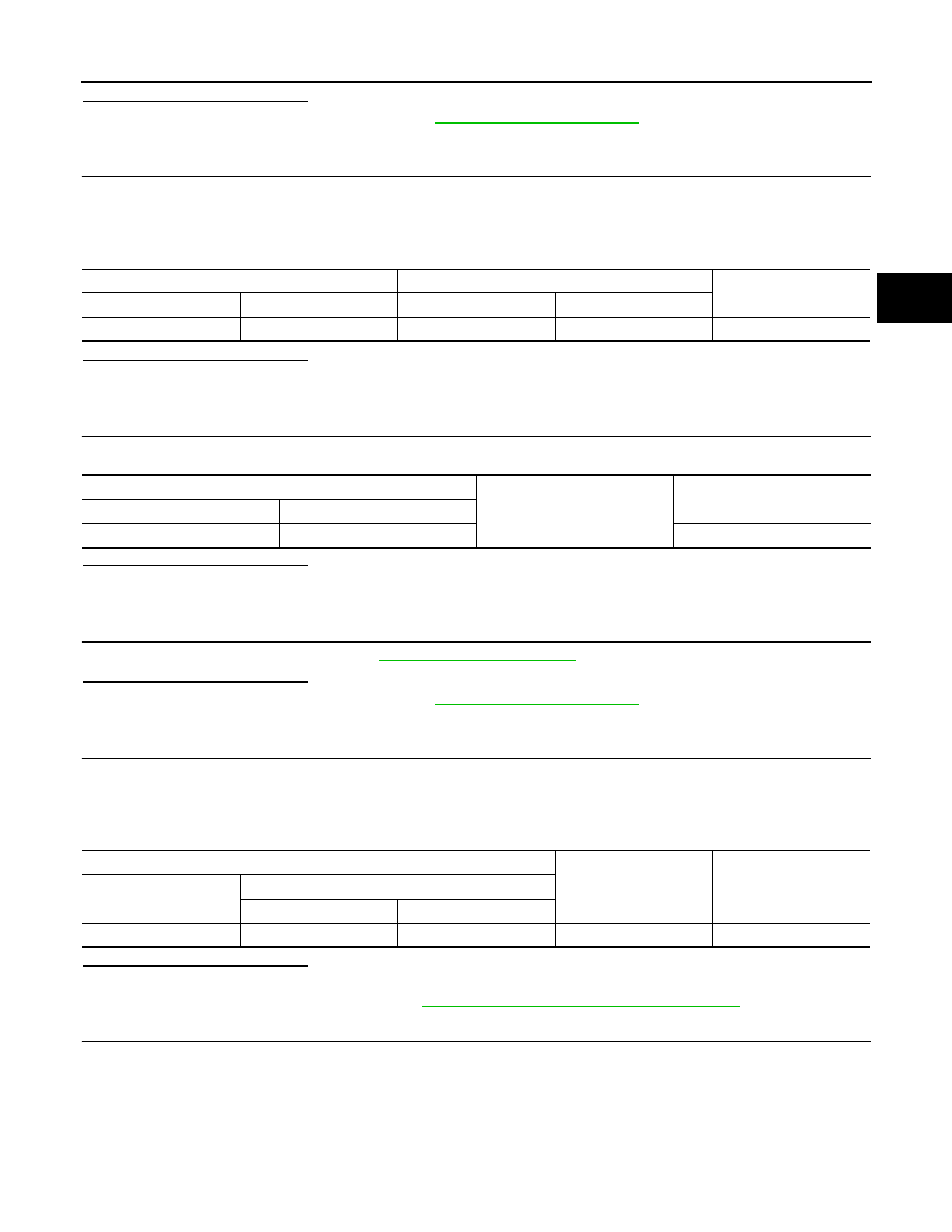
A/T shift selector vehicle side harness connector
BCM vehicle side harness connector
Continuity
Connector
Terminal
Connector
Terminal
M137
10
M122
96
Existed
A/T shift selector vehicle side harness connector
Ground
Continuity
Connector
Terminal
M137
10
Not existed
A/T shift selector vehicle side harness connector
Condition
Voltage (Approx.)
Connector
Terminal
+
−
M137
7
9
Lighting switch 1ST
Battery voltage