Hyundai Santa Fe (2006 year). Manual - part 601
FLA -470
FUEL SYSTEM
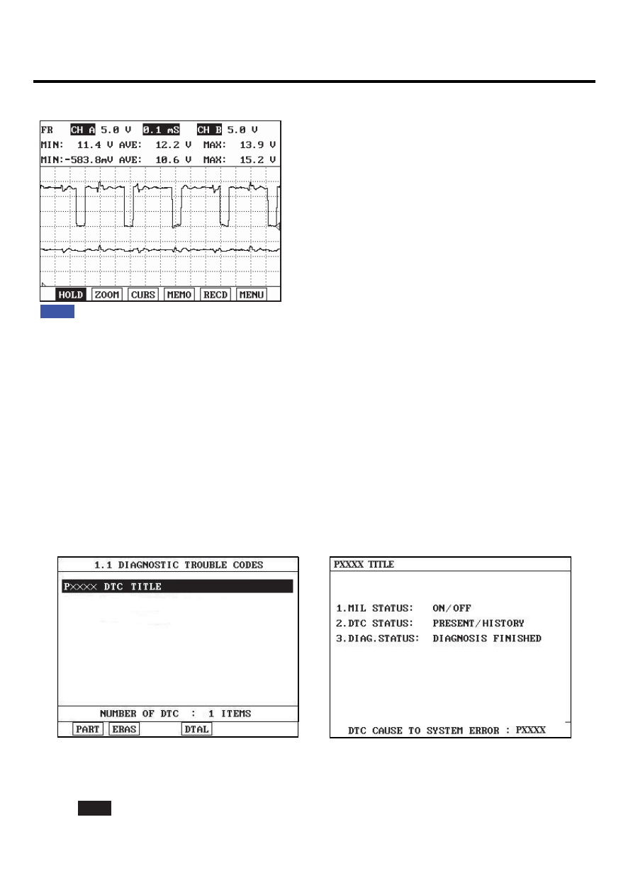
SIGNAL WAVEFORM
E48A6E0B
Fig. 1
Fig1) Signal waveform(+/-) instantly with accelerating
EGRF921A
MONITOR DTC STATUS
EBABB1E4
1.
Check DTC Status
1)
Connect scantool to Data Link Connector(DLC).
2)
IG "ON".
3)
Select "Diagnostic Trouble Codes(DTCs)" mode, and then Press F4(DTAL) to check DTC’s information from the
DTCs menu
4)
Read "DTC Status" parameter.
SCMF16159L
5)
Is parameter displayed "Present fault"?
YES
▶ Go to "Terminal and connector inspection" procedure.