Hyundai Santa Fe (2006 year). Manual - part 577


  Index      Hyundai     Hyundai Santa Fe - service repair manual 2006 year


Search            


Content   ..  575  576  577  578   ..


Hyundai Santa Fe (2006 year). Manual - part 577


FLA -374

FUEL SYSTEM

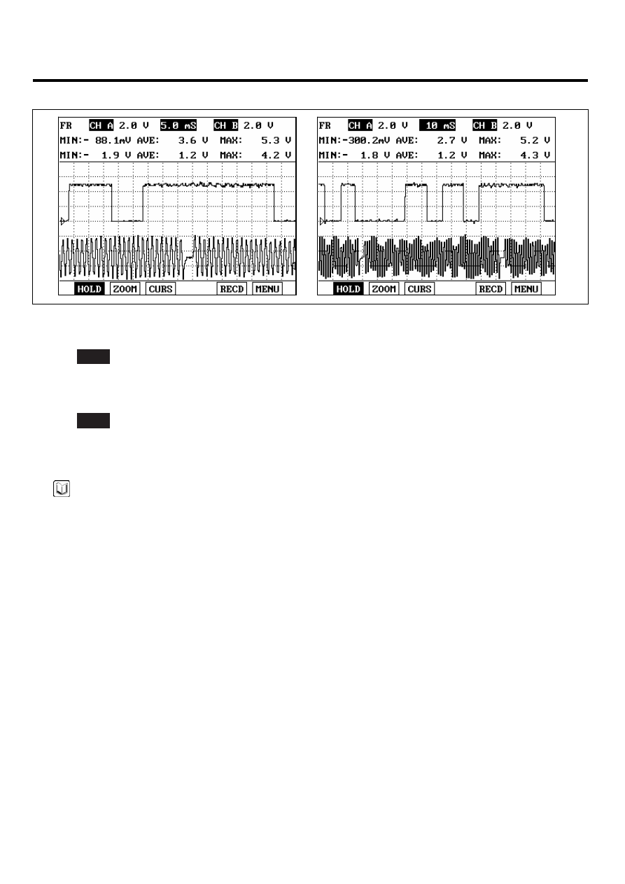
REFERENCE SIGNAL WAVEFORM :

EGRF610K

3)

Is the measured siganl waveform normal?

YES

▶ Thoroughly check connectors for looseness, poor connection, bending, corrosion, contamination, deteriora-
tion, or damage. Repair or replace as necessary, and go to "Verification of Vehicle Repair" procedure.

NO

▶ Substitute with a known - good PCM and check for proper operation. If the problem is corrected, replace PCM
and go to "Verification of Vehicle Repair" procedure.

NOTE

There is a memory reset function on scantool that can erase optional parts automatically detected and memorized
by PCM. After testing PCM on the vehicle, use this function to reuse the PCM on the others

VERIFICATION OF VEHICLE REPAIR

EF39C360

Refer to DTC P0335.

DTC TROUBLESHOOTING PROCEDURES

FLA -375

DTC P0340 CAMSHAFT POSITION SENSOR A CIRCUIT MALFUNCTION
(BANK 1 OR SINGLE SENSOR)

COMPONENT LOCATION

EB1D0C8C

CMPS [Bank 1]

LGLG516A

GENERAL DESCRIPTION

E64D42CB

The Camshaft Position Sensor (CMPS) is a sensor that detects the compression TDC of the NO. 1 cylinder. The CMPS
consists of a hall type sensor and a target on the end of the intake camshaft. When the target triggers the sensor, the
sensor voltage is 5V. If not, the sensor voltage is 0V. These CMPS signal is sent to the ECM and the ECM uses the CMPS
signal for synchronizing the firing of sequential fuel injectors.

DTC DESCRIPTION

EA360937

If PCM detects that cam event signal count is over 3 under detecting condition, PCM sets P0340. MIL(Malfunction Indi-
cation Lamp) turns on when the malfunction lasts till consecutive 2 driving cycle.

DTC DETECTING CONDITION

E7BF5DA1

Item

Detecting Condition

Possible cause

DTC Strategy

• Check if CAM sensor is synchronized correctly

Enable Conditions

• Engine running state

Threshold value

• Cam event signal count ≥ 3

Diagnosis Time

• Continuous

MIL On Condition

• 1 driving cycles

• Poor connection
• Open in harness
• CMPS(Bank 1)
• PCM

FLA -376

FUEL SYSTEM

SCHEMATIC DIAGRAM

EB501374

CMPS [BANK 1]

PCM

C10-1

C30-B

PCM (C30-B)

CMPS [BANK 1]

CMPS [BANK 1] 

(C10-1)

CMPS [BANK 2] 

(C10-2)

1

2

CMPS [BANK 2]

1

2

CMPS [BANK 2]

C10-2

1

2

3

1

2

3

1

21

2

22

3

23

4

24

5

25

6

26

7

27

8

28

9

29

10

30

11

31

12

32

13

33

14

34

15

35

16

36

17

37

18

38

19

39

20

40

41

61

42

62

43

63

44

64

45

65

46

66

47

67

48

68

49

69

50

70

51

71

52

72

53

73

54

74

55

75

56

76

57

77

58

78

59

79

60

80

PCM C30-B (18)

Sensor ground

Reference Voltage

 (+5V)

PCM C30-B (17)

Sensor ground

3

3

PCM C30-B (25)

CMPS [Bank 1] signal

PCM C30-B (24)

PCM C30-B (15)

PCM C30-B (32)

CMPS [Bank 2] signal

Reference Voltage

 (+5V)

18 - GND

32 - Reference Voltage (+5V)

15 - Reference Voltage (+5V)

2

3

25 -  CMPS 

[Bank 1] Signal

1

17 - GND

2

3

24 -  CMPS 

[Bank 2] Signal

1

[CIRCUIT DIAGRAM]

[HARNESS CONNECTORS]

[CONNECTION INFORMATION]

Terminal

Connected to

Function

Terminal

Connected to

Function

SCMF16108L

SIGNAL WAVEFROM AND DATE

E3522305

This example shows a typical Crankshaft Position Sensor(CKPS) and Camshaft Position Sensor(CMPS) waveform at idle. 
The PCM controls the injection and ignition timing by using these signals.  Generally CKPS signal is used to detect the piston’s 
position and CMPS signal is used to detect the Top Dead Center of each cylinder. 

EGRF610R

DTC TROUBLESHOOTING PROCEDURES

FLA -377

MONITOR DTC STATUS

E94F1D1C

1.

Check DTC Status

1)

Connect scantool to Data Link Connector(DLC).

2)

IG "ON".

3)

Select "Diagnostic Trouble Codes(DTCs)" mode, and then Press F4(DTAL) to check DTC’s information from the
DTCs menu

4)

Read "DTC Status" parameter.

SCMF16159L

5)

Is parameter displayed "Present fault"?

YES

▶ Go to "Terminal and connector inspection" procedure.

NO

▶ Fault is intermittent caused by poor contact in the sensor’s and/or PCM’s connector or was repaired and PCM
memory was not cleared. Thoroughly check connectors for looseness, poor connection, ending, corrosion, con-
tamination, deterioration, or damage. Repair or replace as necessary and go to "Verification of Vehicle Repair"
procedure.

TERMINAL AND CONNECTOR INSPECTION

E84D9A8F

1.

Many malfunctions in the electrical system are caused by poor harness and terminals. Faults can also be caused by
interference from other electrical systems, and mechanical or chemical damage.

2.

Thoroughly check connectors for looseness, poor connection, bending, corrosion, contamination, deterioration, or
damage.

3.

Has a problem been found?

YES

▶ Repair as necessary and go to "Verification of Vehicle Repair" procedure

NO


Content   ..  575  576  577  578   ..