Hyundai Santa Fe (2006 year). Manual - part 543


  Index      Hyundai     Hyundai Santa Fe - service repair manual 2006 year


Search            


Content   ..  541  542  543  544   ..


Hyundai Santa Fe (2006 year). Manual - part 543


FLA -238

FUEL SYSTEM

DTC P0131 HO2S CIRCUIT LOW VOLTAGE (BANK 1 / SENSOR 1)
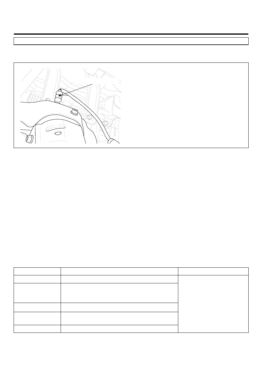
COMPONENT LOCATION

E5E16663

HO2S [Bank 1/Sensor 1]

LGLG504A

GENERAL DESCRIPTION

E9CECC3F

In order to control emissions of the CO, HC and NOx components of the exhaust gas, heated oxygen sensor (HO2S),
mounted on the front side and rear side of catalytic converter, detects the oxygen content in the exhaust gas. The front
HO2S signal is used to control air/fuel ratio (closed loop fuel control) and the rear HO2S signal is used to monitor front
HO2S and catalyst for proper operation. The HO2S requires a minimum temperature to operate properly and provide a
closed loop fuel control system. The HO2S contains the heater element to reduce its warming-up time and ensure its
performance during all driving conditions. The oxygen sensor generates a voltage that indicates the difference between
the oxygen content of the exhaust stream and the oxygen content of ambient air. When the exhaust stream is “ rich,”
there is more oxygen in the ambient air than in the exhaust stream, so the voltage will be higher.

DTC DESCRIPTION

E8D2EB10

Checking output signals from HO2S under detecting condition, if an output signal is below 0.04V for more than predeter-
minate time, PCM sets P0131. MIL(Malfunction Indication Lamp) turns on when the malfunction lasts till consecutive 2
driving cycle.

DTC DETECTING CONDITION

E2DEFF6E

Item

Detecting Condition

Possible cause

DTC Strategy

• Monitor signal voltage

Enable Conditions

• Battery voltage ≥ 10V
• Engine running ≥ 60 sec.
• Engine warm-up state

Threshold value

• The voltage of HO2S(B1/S1) < 0.04V

Diagnosis Time

• Continuous

(more than 12.5 sec. failure for every 15 sec.test)

MIL On Condition

• 2 Driving Cycles

• Poor Connection
• Short to ground in harness
• HO2S(B1/S1)
• PCM

DTC TROUBLESHOOTING PROCEDURES

FLA -239

SPECIFICATION

EB86DDBC

(REFERENCE ONLY)

Test Condition

HO2S Voltage(Sensor1)

HO2S Voltage(Sensor2)

HO2S Signal

at idle after warm-up

Signal is commonly switching

from rich to lean more than 3

times in 10 sec.

Signal is commonly above 0.6V.

HO2S signal at open circuit

(Pumping current OFF)

Approx. 0.45V

HO2S signal at open circuit

(Pumping current ON)

Approx.

3.5V

FLA -240

FUEL SYSTEM

SCHEMATIC DIAGRAM

E57946F9

HO2S [Bank 1/Sensor 1]
HO2S [Bank 2/Sensor 1]

PCM

C91-1,2

C30-B

PCM (C30-B)

HO2S [B1/S1] (C91-1)

1

2

1

21

2

22

3

23

4

24

5

25

6

26

7

27

8

28

9

29

10

30

11

31

12

32

13

33

14

34

15

35

16

36

17

37

18

38

19

39

20

40

41

61

42

62

43

63

44

64

45

65

46

66

47

67

48

68

49

69

50

70

51

71

52

72

53

73

54

74

55

75

56

76

57

77

58

78

59

79

60

80

Battery Voltage (B+)

Main Relay

3

4

PCM C30-B (30)

HO2S [B1/S1] Signal

Sensor ground

PCM C30-B (49)

Main Relay

3

4

1

2

49 - HO2S [B1/S1] Signal

30 - GND

70 - Heater [B1/S1] Control

HO2S [B2/S1] (C91-2)

Main Relay

3

4

1

2

51 - HO2S [B2/S1] Signal

28 - GND

67 - Heater [B2/S1] Control

HO2S [B1/S2] (C91-3)

Main Relay

3

4

1

2

50 - HO2S [B1/S2] Signal

31 - GND

74 - Heater [B1/S2] Control

HO2S [B2/S2] (C91-4)

Main Relay

3

4

1

2

52 - HO2S [B2/S2] Signal

29 - GND

73 - Heater [B2/S2] Control

1

2

3

4

PCM C30-B (28)

HO2S [B2/S1] Signal

Sensor ground

PCM C30-B (51)

Battery Voltage (B+)

Main Relay

PCM C30-B (67)

Heater

 [B2/S1] Control

1

2

3

4

PCM C30-B (31)

HO2S [B1/S2] Signal

Sensor ground

PCM C30-B (50)

Battery Voltage (B+)

Main Relay

PCM C30-B (74)

Heater

 [B1/S2] Control

1

2

3

4

PCM C30-B (29)

HO2S [B2/S2] Signal

Sensor ground

PCM C30-B (52)

Battery Voltage (B+)

Main Relay

PCM C30-B (73)

Heater

 [B2/S2] Control

[CIRCUIT DIAGRAM]

[HARNESS CONNECTORS]

[CONNECTION INFORMATION]

Terminal

Connected to

Function

Terminal

Connected to

Function

Terminal

Connected to

Function

Terminal

Connected to

Function

HO2S [B1/S1]

HO2S [B2/S1]

HO2S [B1/S2]

HO2S [B2/S2]

PCM C30-B (70)

Heater

 [B1/S1] Control

HO2S [Bank 1/Sensor 2]
HO2S [Bank 2/Sensor 2]

C91-3,4

2

1

4

3

1

2

3

4

SCMF16110L

DTC TROUBLESHOOTING PROCEDURES

FLA -241

SIGNAL WAVEFORM AND DATA

E59FF425

Fig) Signal waveforms of front HO2S(the upper) and rear HO2S(the lower)

SCMF16223L

After warming-up, if accelerator pedal is released suddenly around 4000rpm, the HO2S signal reading will be lower than
200mV resulting from Fuel cut-off for the moment. Conversely, if suddenly accelerator pedal is depressed, HO2S signal
reading will be around 0.6V ~1.0V. At idle, Normally HO2S signal will switch from lean to rich with 3 Hz. And as racing,
Its frequency rises.

MONITOR DTC STATUS

EFA6B287

1.

Check DTC Status

1)

Connect scantool to Data Link Connector(DLC).

2)

IG "ON".

3)

Select "Diagnostic Trouble Codes(DTCs)" mode, and then Press F4(DTAL) to check DTC’s information from the
DTCs menu

4)

Read "DTC Status" parameter.

SCMF16159L

5)

Is parameter displayed "Present fault"?


Content   ..  541  542  543  544   ..