Hyundai Santa Fe (2006 year). Manual - part 506


  Index      Hyundai     Hyundai Santa Fe - service repair manual 2006 year


Search            


Content   ..  504  505  506  507   ..


Hyundai Santa Fe (2006 year). Manual - part 506


FLA -90

FUEL SYSTEM

3)

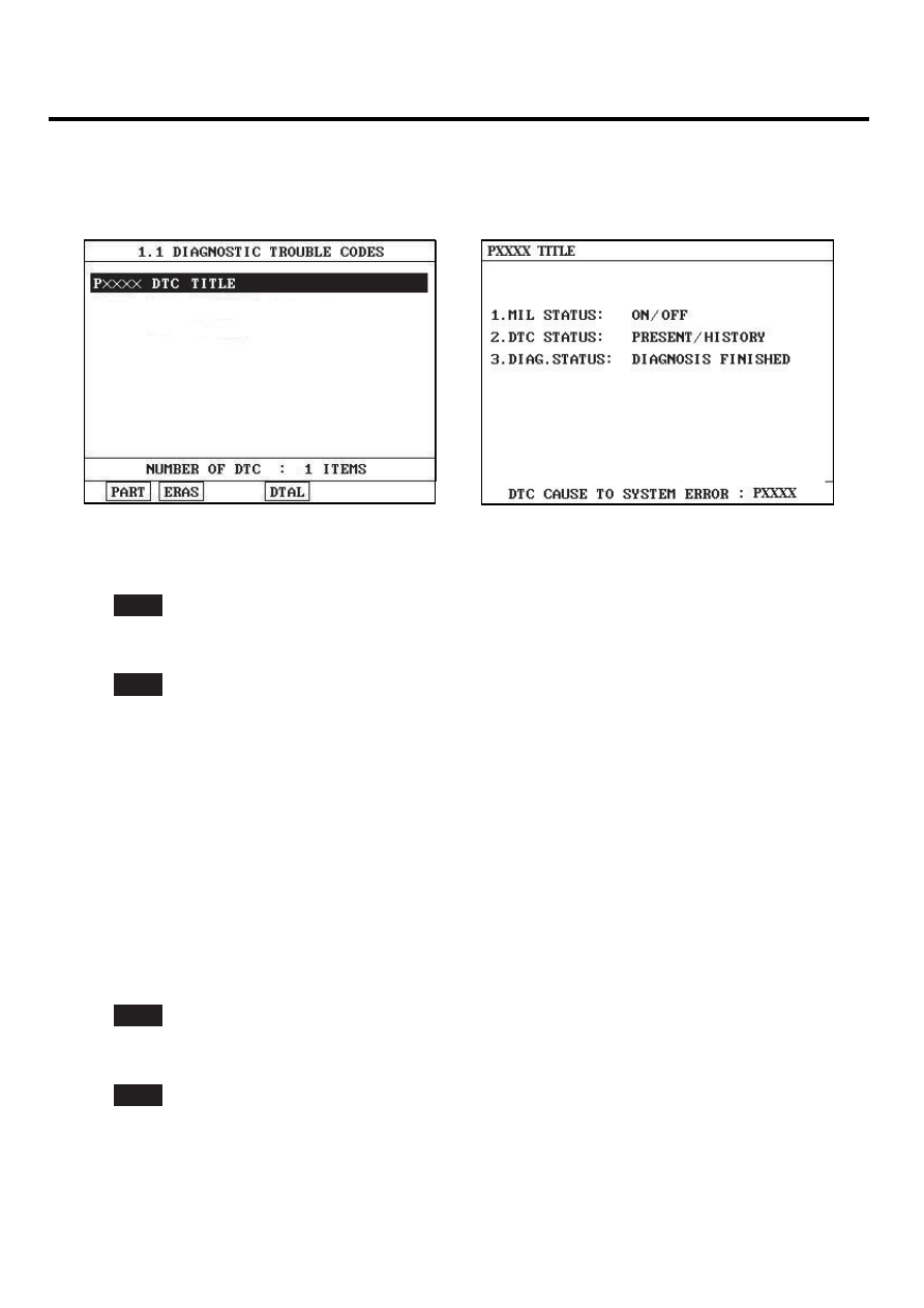
Select "Diagnostic Trouble Codes(DTCs)" mode, and then Press F4(DTAL) to check DTC’s information from the
DTCs menu

4)

Read "DTC Status" parameter.

SCMF16159L

5)

Is parameter displayed "Present fault"?

YES

▶ Go to "System Inspection" procedure.

NO

▶ Fault is intermittent caused by poor contact in the sensor’s and/or PCM’s connector or was repaired and PCM
memory was not cleared. Thoroughly check connectors for looseness, poor connection, ending, corrosion, con-
tamination, deterioration, or damage. Repair or replace as necessary and go to "Verification of Vehicle Repair"
procedure.

SYSTEM INSPECTION

E77A6F95

1.

Visual Inspection

1)

Check oil level is O.K.

2)

Check oil is contaminated.

3)

Has a problem been found ?

YES

▶ Repair or replace as necessary and then, go to " Verification of Vehicle Repair" procedure.

NO

▶ Go to "Component Inspection" procedure.

COMPONENT INSPECTION

E696E30F

1.

Check OCV

DTC TROUBLESHOOTING PROCEDURES

FLA -91

1)

Connect scantool and IG "ON"

2)

Select "OCV" on the Actuation Test

3)

Activate "OCV" by pressing "STRT(F1)" key
(should hear a faint click from Oil Control solenoid Valve)

4)

Repeat this procedure 4 or 5 times to ensure reliability

EGRF600H

5)

Has a problem been found ?

YES

▶ Substitute with a known - good OCV and check for proper operation. If the problem is corrected, replace OCV
and go to "Verification of Vehicle Repair" procedure.

NO

▶ Substitute with a known - good CVVT and check for proper operation. If the problem is corrected, replace
CVVT and go to "Verification of Vehicle Repair" procedure.

VERIFICATION OF VEHICLE REPAIR

ED5C3394

After a repair, it is essential to verify that the fault has been corrected.

1.

Monitor and record the Freeze Frame Data for the Diagnostic Trouble Code(DTC) which has been diagnosed.

2.

Using a Scantool, Clear the DTCs

3.

Operate the vehicle within conditions noted in the freeze frame data or enable conditions

4.

Monitor that all rediness test have been verified as " Complete "

5.

Are any DTCs present ?

YES

▶ Go to the applicable troubleshoooting procedure.

NO

▶ System is performing to specification at this time.

FLA -92

FUEL SYSTEM

DTC P0016 CRANKSHAFT POSITION-CAMSHAFT POSITION CORRELATION
(BANK 1 SENSOR A)

COMPONENT LOCATION

EAA97372

CKPS

CMPS [Bank 1]

LGLG501A

GENERAL DESCRIPTION

E10B26F9

The CVVT (Continuously Variable Valve Timing) system is installed to the chain sprocket of the intake camshaft. This
system controls the intake camshaft to provide the optimal valve timing for every driving condition. The ECM controls the
Oil Control Valve(OCV), based on the signals output from mass air flow, throttle position and engine coolant temperature.
The CVVT controller regulates the intake camshaft angle using oil pressure through the OCV. As result, the relative posi-
tion between the camshaft and the crankshaft becomes optimal, and the engine torque improves, fuel economy improves,
exhaust emissions decrease under overall driving conditions.

DTC DESCRIPTION

EAEA7CB5

Tooth offsets are learned, updated, stored and initialized. For a given cam target wheel and systemcalibration, the tooth
offsets should maintain relatively steady values. If the values of tooth offsets are observed to drift outside of an established
range, then a failure is present for measuring cam phasing.
This diagnosis is to verify that learned tooth offsets are within an acceptable range.
PCM monitors tooth offset while no active faults is present.If the tooth offsets is out of threshold during more than 6 offset
learning for 36 offset learning, PCM determines that a fault exists and a DTC is stored.

DTC TROUBLESHOOTING PROCEDURES

FLA -93

DTC DETECTING CONDITION

EB7F927C

Item

Detecting Condition

Possible cause

DTC Strategy

• Determines if CAM target is aligned correctly to crank

Enable Conditions

• No active faults

Case 1

• Real Offset Value 〈 Min. Cam Offset

programmed in PCM

Thresh

old value

Case 2

• Real Offset Value 〉 Max. Cam Offset

programmed in PCM

Diagnosis Time

• Continuous

(More than 6 offset learning failure for 36
offset learning )

MIL On Condition

• 2 driving Cycles

• CKPS, CMPS
• CVVT
• Timing Misalignment
• PCM

SCHEMATIC DIAGRAM

E40CE2FC

3

Sensor Shield

Chassis Ground

CKPS

PCM

C01

C30-B

PCM (C30-B)

CKPS (C01)

1

2

1

21

2

22

3

23

4

24

5

25

6

26

7

27

8

28

9

29

10

30

11

31

12

32

13

33

14

34

15

35

16

36

17

37

18

38

19

39

20

40

41

61

42

62

43

63

44

64

45

65

46

66

47

67

48

68

49

69

50

70

51

71

52

72

53

73

54

74

55

75

56

76

57

77

58

78

59

79

60

80

PCM C30-B (21)

CKPS [LOW]

 Signal

CKPS [HIGH]

 Signal

PCM C30-B (41)

21 - CKPS [HIGH]

41 - CKPS [LOW]

1

2

3

S

N

[CIRCUIT DIAGRAM]

[HARNESS CONNECTORS]

[CONNECTION INFORMATION]

Terminal

Connected to

Function

1

2

3

SCMF16109L


Content   ..  504  505  506  507   ..