Hyundai Santa Fe (2006 year). Manual - part 503
FLA -78
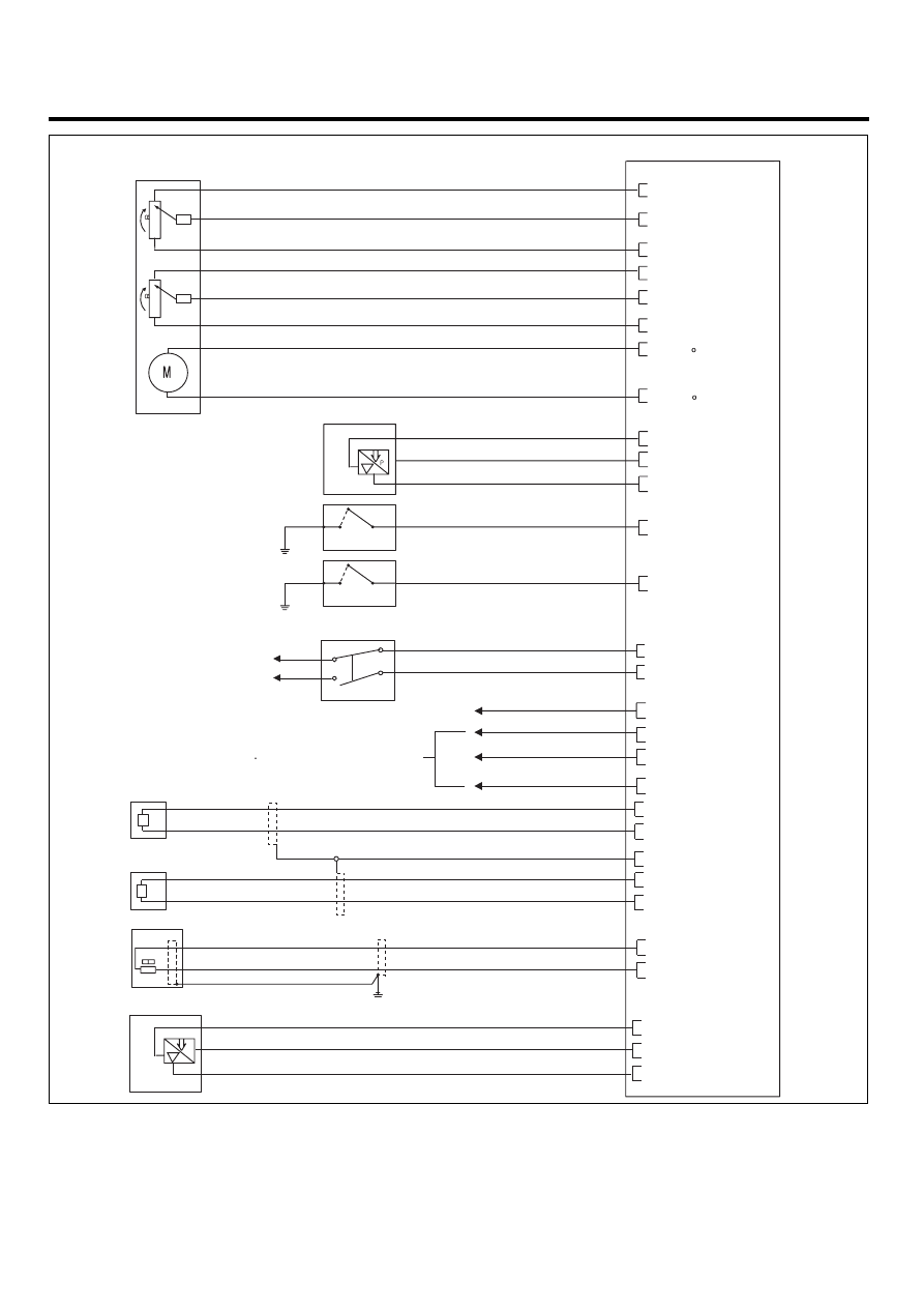
FUEL SYSTEM
P C M
B16 - Reference voltage (+5V)
B13 - Reference voltage (+5V)
B48 - TPS1 signal input
B14 - Sensor ground
B57 - TPS2 signal input
B58 - Sensor ground
B2 - ETC Mot r (+) control
B1 - ETC Mot r (-) control
A33 - Sensor ground
A58 - Reference voltage (+5V)
A32 - Sensor signal input
A10 - Power Steering Pressure
Switch signal input
A23 - Brake lamp signal input
A21 - Brake switch signal input
A15 - Alternator load signal input
A26 - A/C blower switch signal input
A64 - A/C compressor relay control
A18 - A/C switch "ON" signal input
B55 - KS [Bank 1] [LOW] signal input
B54 - KS [Bank 2] [LOW] signal input
B56 - KS [Bank 1] [HIGH] signal input
B53 - KS [Bank 2] [HIGH] signal input
B21 - CKPS [HIGH] signal input
B41 - CKPS [LOW] signal input
B34 - Sensor ground
B8 - MAPS signal input
B11 - Reference voltage (+5V)
B23 - Sensor shield
ETC MODULE
4
2
1
7
3
6
5
8
TPS2
TPS1
ETC MOTOR
A/C PREESSURE SENSOR
BRAKE SWITCH
ALTERNATOR
Refer to "Electrical Troubleshooting Manual"
KS [BANK 1]
KS [BANK 2]
CKPS
MAPS
Battery(+)
IG ON
2
1
3
4
1
3
2
P
1
2
1
2
3
1
4
2
2
1
S
N
POWER STEERING
PRESSURE SWITCH
A13 - Clutch Switch signal input
CLUCH SWITCH
SCMF16129L