Hyundai Santa Fe (2006 year). Manual - part 502
FLA -74
FUEL SYSTEM
Pin
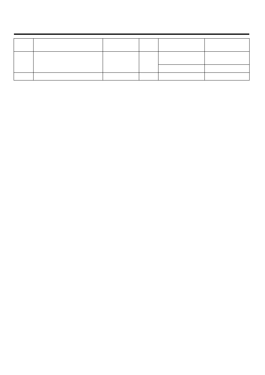
No.
Description
Condition
Type
Level
Test Result
1st Voltage:
200~400V
269V
79
Ignition Coil (Cylinder #1)
control output
Idle
Pulse
ON Voltage: Max. 2V
1.91V
80
-
|
|
|
FLA -74 FUEL SYSTEM Pin No. Description Condition Type Level Test Result 1st Voltage: 200~400V 269V 79 Ignition Coil (Cylinder #1) Idle Pulse ON Voltage: Max. 2V 1.91V 80 - |