Hyundai Santa Fe (2006 year). Manual - part 490
FLA -26
FUEL SYSTEM
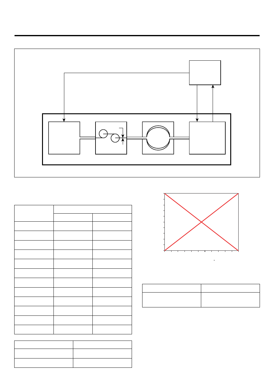
SHEMATIC DIAGRAM
PCM
ETC Motor
Throttle
Valve
TPS 1
TPS 2
Motor Operation Signal
ETC Module
Power
Supply
(+5V)
Throttle Position
Sensor (TPS)
Gear Housing
F
EGRF234A
SPECIFICATION
[THROTTLE POSITION SENSOR]
Output Voltage(V) [Vref = 5.0V]
Throttle
Angle(˚ )
TPS1
TPS2
0˚
0V
5.0V
10˚
0.5V
4.5V
20˚
0.9V
4.1V
30˚
1.4V
3.6V
40˚
1.8V
3.2V
50˚
2.3V
2.7V
60˚
2.7V
2.3V
70˚
3.2V
1.8V
80˚
3.6V
1.4V
90˚
4.1V
0.9V
100˚
4.5V
0.5V
110˚
5.0V
0V
Item
Sensor Resistance
TPS1
4.0 ~ 6.0㏀ at 20℃ (68℉)
TPS2
2.7 ~ 4.1㏀ at 20℃ (68℉)
[TPS CHARACTERISTIC GRAPH]
Throttle Angle ( )
TPS1
TPS2
Output V
oltage
(V
)
90
80
70
60
50
40
30
20
10
0
0
10
20
30
40
50
70
80
90 100 110
EGRF235A
[ETC MOTOR]
Item
Sensor Resistance
Coil Resistance (Ω )
1.275 ~ 1.725Ω at
20℃ (68℉)