Hyundai Santa Fe (2006 year). Manual - part 437


  Index      Hyundai     Hyundai Santa Fe - service repair manual 2006 year


Search            


Content   ..  435  436  437  438   ..


Hyundai Santa Fe (2006 year). Manual - part 437


FL -358

FUEL SYSTEM

2)

Disconnect A/CON relay.

3)

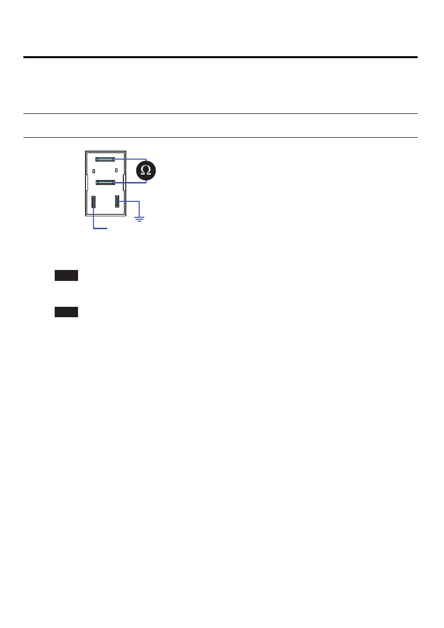
Supplies random B+ and ground to coil sides of A/C relay ( terminal 85, terminal 86).

4)

Check continuity between A/C relay terminal 30 and terminal 87.

specification : When power is supplied : Continuity ( below 1.0

)

When power is not supplied : Discontinuity ( Infinite

)

30

87

86

85

B+

EGNG001I

5)

Is the continuity test within the specification?

YES

Go to "Verification of Vehicle Repair".

NO

Replace A/CON relay and go to "Verification of Vehicle Repair".

Repeat this process 2~3 times.

VERIFICATION OF VEHICLE REPAIR

E33F5D68

Refer to DTC P0646.

DTC TROUBLESHOOTING PROCEDURES

FL -359

DTC P0650 MALFUNCTION INDICATOR LAMP(MIL) CONTROL CIRCUIT

GENERAL DESCRIPTION

E3CFDE6C

As monitoring the errors of several sensors and actuator circuit, TCM related problem and ECM error, if any problem
occurs, ECM turns Engine Check Lamp ON at cluster to notify driver the occurence of a problem. Generally, Engine
Check Lamp turns ON at Ignition ON and turns OFF within couple of seconds after turning engine ON. If engine check
lamp turns on during driving, perform diagnosis of engine system and auto-transaxle system.

DTC DESCRIPTION

E01ACF53

P0650 is set when 1)excessive current is detected in engine check lamp control circuit for more than 2 sec.. at engine
check lamp ON condition or 2)like open or short to ground, no current is detected. This code is due to open in control
circuit or opened filament of lamp component.

DTC DETECTING CONDITION

EF1E1552

Item

Detecting Condition

Possible Cause

DTC Strategy

• Voltage monitoring

Enable Conditions

• IG KEY "ON" (Monitoring only performed within

lamp operating condition)

Threshold Value

• Short to battery
• Short to GND, Wiring open

Diagnostic Time

• 2 sec.

Fuel cut

NO

EGR Off

NO

Fuel Limit

NO

Fail Safe

Check

Lamp

NO

• Open in engine check lamp
• Engine check lamp circuit.

FL -360

FUEL SYSTEM

SCHEMATIC DIAGRAM

E20DEEC4

M15-B terminal 15

M15-A terminal 10

10A CLUSTER FUSE

IG power

Engine check lamp control

C230-K terminal 68

10A CLUSTER FUSE (IG power)

ECM (C230-K)

M15 Cluster

Engine check lamp

M15-A (10)

M15-B (15)

C230-K

C230-A

68 Engine check lamp control

1

2

4

3

6

5

8 7

12

13

16

17

18

23 22

20

21

19

27 26 25 24

28

29

30

14

9

10

11

15

33 32 31

34

37

41

42

40 39 38

35

36

43

44

47 46

49 48

50

53

56

58 57

54

51

52

55

59

60
45

M15-A

Cluster

M15-B

Cluster

ECM

MIL

1

2

6

7

4

3

10

9

16 15

12

13

11

18

19

20

17

1

2

3

4

5

5

6

7

8

8

9

10

11

12

13

14

14

15

16

73

51

29

7

1

2

3

4

5

6

74

52

30

8

75

77

53

35

36

37

34 33 32 31

9

76

54

10

55

11

78

56

12

79

57

13

80

58

14

81

59

15

82

60

38

16

83

61

39

17

84

62

40

18

85

63

41

19

86

64

42

20

87

65

43

21

88

66

22

89

67

45 44

23

90

68

46

24

91

69

47

25

92

70

48

26

93

71

49

27

94

72

50

28

[CIRCUIT DIAGRAM]

[HARNESS CONNECTOR]

[CONNECTOR INFORMATION]

Terminal

Connected to

Function

SCMFL6405L

TERMINAL AND CONNECTOR INSPECTION

E5CAECA4

1.

Electrical systems consist of a lot of harness and connectors, poor connection of terminals can cause various prob-
lems and damge of component.

2.

Perform checking procedure as follows.

1)

Check damage of harness and terminals : Check terminals for contact resistance, corrosion and deformation.

2)

Check connecting condition of ECM and component connector : Check terminal seperation, damage of locking
device and connecting condition between terminal and wiring.

NOTE

Disconnect the pin which requires checking at male connector and insert it to the terminal at female connector for
checking connecting condition. ( after checking, reconnect the pin at correct position. )

3.

Is the problem found?

YES

Repair the trouble causing part and go to "Verification of Vehicle Repair".

NO

DTC TROUBLESHOOTING PROCEDURES

FL -361

Go to "Control Circuit Inspection".

CONTROL CIRCUIT INSPECTION

E7DF2DCD

1.

Check control circuit voltage

1)

IG KEY "OFF", ENGINE "OFF".

2)

Disconnect ECM connector.

3)

IG KEY "ON".

4)

Measure the voltage of terminal 68 of ECM connector (C230-K).

Specification : 10.8V~13.0V

5)

Is the measured voltage within the specification?

YES

Go to "2. Grounding test of check lamp control circuit" as follows.

NO

Check open in filament of check lamp. ( Refer to Component Inspection)

Repair open between cluster connector(M15-A) terminal 10 and ECM connector(C230-K) terminal 68 and go

to "Verification of Vehicle Repair",

2.

Grounding test of check lamp control circuit

1)

IG KEY "OFF", ENGINE "OFF".

2)

Disconnect ECM connector.

3)

IG KEY "ON".

4)

Ground ECM connector (C230-K) terminal 68 to chassis ground.

specification : check lamp turns ON.

5)

Does check lamp turn ON?

YES

Go to "Verification of Vehicle Repair".

NO

Repair short to battery in check lamp control circuit and go to "Verification of Vehicle Repair".

COMPONENT INSPECTION

ECE5AC65

1.

IG KEY "OFF", ENGINE "OFF".

2.

Dismount cluster and disconnect check lamp.

3.

Check filament of check lamp.


Content   ..  435  436  437  438   ..