Hyundai Santa Fe (2006 year). Manual - part 435
FL -350
FUEL SYSTEM
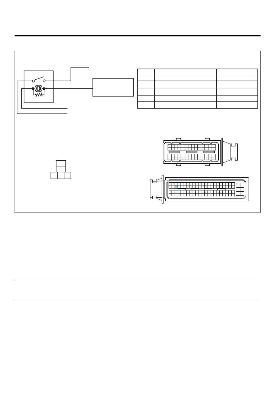
SCHEMATIC DIAGRAM
EA097066
C230-A
C230-K
1
2
4
3
6
5
8 7
12
13
16
17
18
23 22
20
21
19
27 26 25 24
28
29
30
14
9
10
11
15
33 32 31
34
37
41
42
40 39 38
35
36
43
44
47 46
49 48
50
53
56
58 57
54
51
52
55
59
60
45
ECM
73
51
29
7
1
2
3
4
5
6
74
52
30
8
75
77
53
35
36
37
34 33 32 31
9
76
54
10
55
11
78
56
12
79
57
13
80
58
14
81
59
15
82
60
38
16
83
61
39
17
84
62
40
18
85
63
41
19
86
64
42
20
87
65
43
21
88
66
22
89
67
45 44
23
90
68
46
24
91
69
47
25
92
70
48
26
93
71
49
27
94
72
50
28
[CIRCUIT DIAGRAM]
[HARNESS CONNECTOR]
[CONNECTOR INFORMATION]
1
5
2
3
Relay power(INPUT)
Relay power(OUTPUT)
Relay coil power
Relay control
E201 A/C compressor
A/C compressor
70 A/C relay control
A/C relay
A/C relay
C230-K terminal 70
10A A/CON FUSE(Hot at all times)
10A A/CON FUSE(Hot at all times)
15A INJ FUSE(Main relay power)
15A INJ FUSE(Main relay power)
C230-K ECM
Terminal
Connected to
Function
1
2
3
4
5
1
2
3
5
*
*
*
SCMFL6404L
MONITOR SCANTOOL DATA
E2DFAF58
1.
Connect scantool to Data Link Cable (DLC).
2.
Warm engine up to normal operating temperature.
3.
Turn "OFF" electrical devices and A/C.
4.
Monitor "A/C COMPRESSOR CONTROL" parameter on the scantool.
specification : A/C switch "ON" : A/C RELAY "ON" (Aircon compressor turns ON and OFF
periodically by Aircon pressure S/W. )
A/C switch "OFF" : A/C RELAY "OFF"