Hyundai Santa Fe (2006 year). Manual - part 423
 

  Index      Hyundai     Hyundai Santa Fe - service repair manual 2006 year


Search            


Content   ..  421  422  423  424   ..


Hyundai Santa Fe (2006 year). Manual - part 423


FL -302

FUEL SYSTEM

SCHEMATIC DIAGRAM

EA387AD9

Brake S/W 1 signal

Main relay power

Hot at all times

Brake S/W 2 signal

Main relay power(10A SENSOR #1 FUSE)

Hot at all times
(I/P JUNCTION BOX 15A STOP LP FUSE)

80. Brake S/W 2 signal

38. Brake S/W 1 signal

C254 Brake S/W

 Brake S/W

C254

C230-K ECM

1

2

2

1

4

3

3

4

Terminal

Connected to

Function

C230-K terminal 38

15A STOP LP FUSE

10A SENSOR #1 FUSE

C230-K terminal 80

1

2

4

3

C230-K

C230-A

1

2

4

3

6

5

8 7

12

13

16

17

18

23 22

20

21

19

27 26 25 24

28

29

30

14

9

10

11

15

33 32 31

34

37

41

42

40 39 38

35

36

43

44

47 46

49 48

50

53

56

58 57

54

51

52

55

59

60
45

ECM

1

30 29

31

32

38

39

36

37

35

33

34

40

42 41

46 45 44 43

48 47

50 49

2

3

4

6

5

8

7

12 11 10 9

13

14

15

18 17

19

16

22

25

27 26

23

20

21

24

28

51

75 74
53 52

73

79 78 77 76

80

81

83 82

84

86 85

87

89 88

90

92 91

93

94

57

69 68

70

71

64

54

55

56

61

58

59

60

63 62

65

66

67

72

[CIRCUIT DIAGRAM]

[HARNESS CONNECTOR]

[CONNECTOR INFORMATION]

SCMFL6401L

SIGNAL WAVEFORM AND DATA

EF4BE3CA

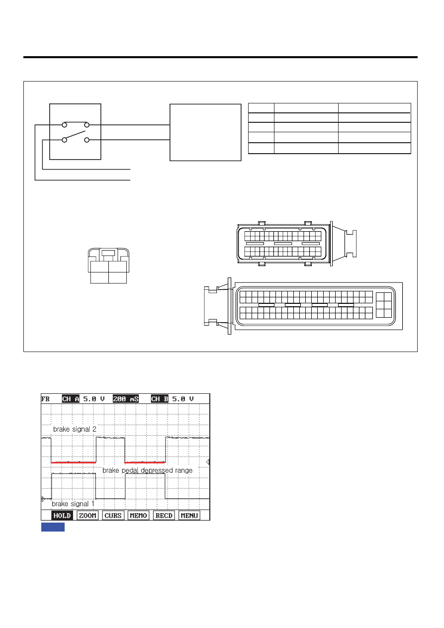
Fig.1) The waveform of brake signal 1 and 2 are measured simultaneously. Both waveforms are symmetrical.

Fig.1

LFIG313A

DTC TROUBLESHOOTING PROCEDURES

FL -303

MONITOR SCANTOOL DATA

E36704C3

1.

Connect Scantool to Data Link Connector (DLC).

2.

Warm engine up to normal operating temperature.

3.

Turn "OFF" electrical devices and A/C.

4.

Monitor "BRAKE SWITCH" and "REDUNDANT BRAKE SWITCH" parameter on the Scantool.

specification : When brake pedal is released : "BRAKE SWITCH" and "REDUNDANT BRAKE SWITCH" : OFF
When brake pedal is depressed : "BRAKE SWITCH" and "REDUNDANT BRAKE SWITCH" : ON

Fig.1) Data when brake switch(brake pedal) is deactivated(released) : 
          "BRAKE SWITCH" and "REDUNDANT BRAKE SWITCH" : OFF 
Fig.2) Data when brake switch(brake pedal) is activated(depressed) : 
          "BRAKE SWITCH" and "REDUNDANT BRAKE SWITCH" : ON

Fig.1

Fig.2

LFIG314A

TERMINAL AND CONNECTOR INSPECTION

E989CFB5

1.

Electrical systems consist of a lot of harness and connectors, poor connection of terminals can cause various prob-
lems and damge of component.

2.

Perform checking procedure as follows.

1)

Check damage of harness and terminals : Check terminals for contact resistance, corrosion and deformation.

2)

Check connecting condition of ECM and component connector : Check terminal seperation, damage of locking
device and connecting condition between terminal and wiring.

NOTE

Disconnect the pin which requires checking at male connector and insert it to the terminal at female connector for
checking connecting condition. ( after checking, reconnect the pin at correct position. )

3.

Is the problem found?

YES

Repair the trouble causing part and go to "Verification of Vehicle Repair".

NO

FL -304

FUEL SYSTEM

Go to "Power Circuit Inspection".

POWER CIRCUIT INSPECTION

E369C6F6

1.

Check brake switch 1 "HOT AT ALL TIMES"

1)

IG KEY "OFF", ENGINE "OFF".

2)

Disconnect brake switch connector.

3)

Measure the voltage of terminal 1 of brake switch connector.

Specification : 11.5V~13.0V

4)

Is the measured voltage within the specification?

YES

Go to "2.Check brake switch 2 main relay power" as follows.

NO

Repair I/P JUNCTION BOX 15A STOP LP FUSE and related circuit and go to "Verification of Vehicle Repair".

2.

Check brake switch 2 main relay power

1)

IG KEY "OFF", ENGINE "OFF".

2)

Disconnect brake switch connector.

3)

IG KEY "ON".

4)

Measure the voltage of brake switch connector terminal 3.

Specification : 11.5V~13.0V

5)

Is the measured voltage within the specification?

YES

Go to "Signal Circuit Inspection".

NO

Repair E/R FUSE

RELAY BOX 10A SENSOR #1 FUSE and related circuit and go to "Verification of Vehicle

Repair".

SIGNAL CIRCUIT INSPECTION

EBEAD6E4

1.

Check brake switch signal circuit voltage

1)

IG KEY "OFF", ENGINE "OFF".

2)

Disconnect ECM connector with brake switch connector connected.

3)

Disconnect E/R FUSE & RELAY BOX main relay, connect main relay terminal 1 and 5 using jump wire.

4)

Measure the voltage of ECM connector (C230-K) terminals 38 and 80 as depressing brake pedal.

DTC TROUBLESHOOTING PROCEDURES

FL -305

SPECIFICATION :

Brake Pedal Released

Brake Pedal Depressed

Brake switch 1 (terminal 38)

0.0V~0.1V

11.5V~13.0V

Brake switch 2 (terminal 80)

11.5V~13.0V

0.0V~0.1V

5)

Is the measured voltage within the specification?

YES

Go to "2. Check open in signal circuit".

NO

Go to "Component Inspection".

2.

Check open in signal circuit

1)

IG KEY "OFF", ENGINE "OFF".

2)

Disconnect brake switch connector and ECM connector.

3)

Check continuity between brake switch connector terminal 2 and ECM connector (C230-K) terminal 38. (brake
switch 1 circuit)

4)

Check continuity between brake switch connector terminal 4 and ECM connector (C230-K) terminal 80. (brake
switch 2 circuit)

specification : Continuity ( below 1.0

)

5)

Is the measured resistance within the specification?

YES

Repair short in signal circuit and go to "Verification of Vehicle Repair".

NO

Repair open in signal circuit and go to "Verification of Vehicle Repair".

COMPONENT INSPECTION

E5469650

1.

IG KEY "OFF", ENGINE "OFF".

2.

Disconnect brake switch connector.

3.

Check continuity between brake switch component terminal 1and 2 as depressing brake pedal. (brake switch 1)

4.

Check continuity between brake switch component terminal 3and 4 as depressing brake pedal. (brake switch 2)

SPECIFICATION :

Brake Pedal Released

Brake Pedal Depressed

Switch 1

Switch 2

Switch 1

Switch 2

Discontinuity

Continuity

Continuity

Discontinuity


Content   ..  421  422  423  424   ..