Hyundai Santa Fe (2006 year). Manual - part 356


  Index      Hyundai     Hyundai Santa Fe - service repair manual 2006 year


Search            


Content   ..  354  355  356  357   ..


Hyundai Santa Fe (2006 year). Manual - part 356


FL -34

FUEL SYSTEM

3.

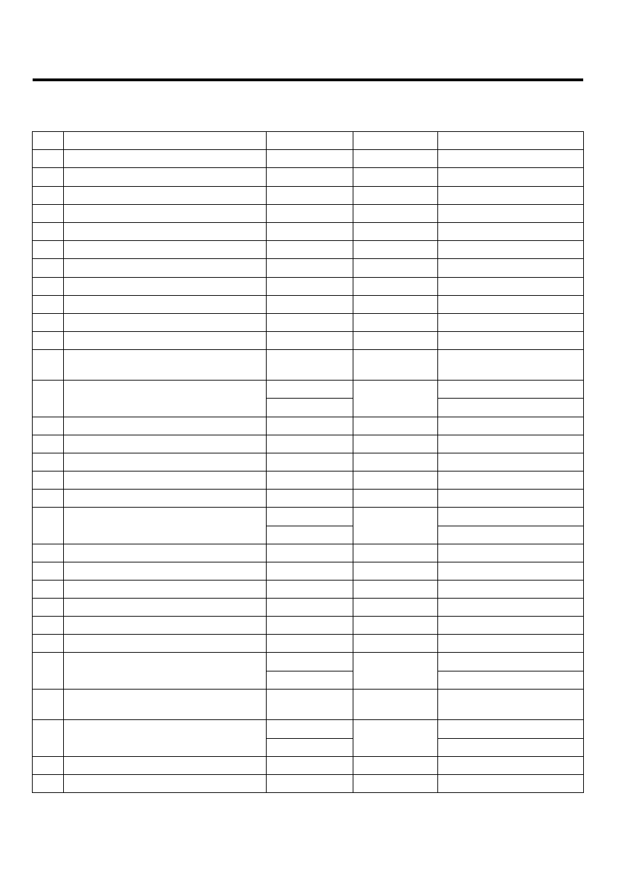
ECM TERMINAL INPUT/OUTPUT SIGNAL

CONNECTOR [C230-A]

Pin

Description

Type

Vehicle State

Level

1

Injector (Cylinder #3) [HIGH] control output

Idle

Pulse

B+ ~ 80V

2

Injector (Cylinder #2) [HIGH] control output

Idle

Pulse

B+ ~ 80V

3

-

-

-

-

4

Battery power

Idle

DC

Vbatt

5

-

-

-

-

6

Sensor ground

Idle

DC

Max. 50mV

7

Sensor shield

Idle

DC

Max. 50mV

8

Sensor ground

Idle

DC

Max. 50mV

9

-

-

-

-

10

-

-

-

-

11

-

-

-

-

12

Crankshaft Position Sensor (CKPS)
[-] signal input

Idle

Sine Wave

Vp_p : Min.1.0V

IG OFF

Max. 0.5V

13

Reference voltage (+5V)

IG ON

DC

4.9 ~ 5.1V

14

-

-

-

-

15

-

-

-

-

16

Injector (Cylinder #1) [HIGH] control output

Idle

Pulse

Vbatt ~ 80V

17

Injector (Cylinder #4) [HIGH] control output

Idle

Pulse

Vbatt ~ 80V

18

-

-

-

-

IG OFF

Max. 0.5 V

19

Battery power

IG ON

DC

Vbatt

20

Sensor ground

Idle

DC

Max. 50 mV

21

-

-

-

-

22

-

-

-

-

23

Sensor ground

Idle

DC

Max. 50 mV

24

-

-

-

-

25

-

-

-

-

IG OFF

Max. 0.5V

26

Reference voltage (+5V)

IG ON

DC

4.9 ~ 5.1V

27

Crankshaft Position Sensor (CKPS)
[+] signal input

Idle

Sine Wave

Vp_p : Min.1.0V

IG OFF

Max. 0.5V

28

Reference voltage (+5V)

IG ON

DC

4.9 ~ 5.1V

29

-

-

-

-

30

Motor [-] control output

Active

DC

Max.0.5V

DIESEL CONTROL SYSTEM

FL -35

Pin

Description

Type

Vehicle State

Level

31

Injector (Cylinder #2) [LOW] control output

Idle

Current

Peak Current : 19 ~ 21 A

Hold Current : 11~ 13 A

19 ~ 21A

11 ~ 13A

EFQG102A

32

-

-

-

-

33

Injector (Cylinder #4) [LOW] control output

Idle

Current

Peak Current : 19 ~ 21 A

Hold Current : 11~ 13 A

19 ~ 21A

11 ~ 13A

EFQG102A

34

Rail Pressure Regulator Valve
control output

Idle

Current

Hi: Vbatt

Lo: Max. 1.0V Frequency

= 1kHz ± 2%

35

-

-

-

-

36

-

-

-

-

37

Reference frequency

Idle

Pulse

Hi: Vcc or Vbatt

Lo: Max. 1.0V

38

-

-

-

-

39

-

-

-

-

40

Boost Pressure Sensor (BPS) signal input

IG ON

Analog

0.5 ~ 4.5V

41

Sensor ground

Idle

DC

Max. 50 mV

42

Mass Air Flow Sensor (MAFS) signal input

Idle

Pulse

Hi: Vcc or Vbatt

Lo: Max. 1.0V

IG ON

Max. 1.0V

Idle

1.0 ~ 1.5 V

43

Rail Pressure Sensor (RPS) signal input

3000 RPM

Analog

1.5 ~ 3.0 V

44

Sensor ground

Idle

DC

Max. 50 mV

Relay OFF

Vbatt

45

Fuel Pump Relay output

Relay ON

DC

Max. 1.0V

46

Injector (Cylinder #3) [LOW] control output

Idle

Current

Peak Current : 19 ~ 21 A

Hold Current : 11~ 13 A

19 ~ 21A

11 ~ 13A

EFQG102A

47

Injector (Cylinder #1) [LOW] control output

Idle

Pulse

Peak Current : 19 ~ 21 A

Hold Current : 11~ 13 A

19 ~ 21A

11 ~ 13A

EFQG102A

FL -36

FUEL SYSTEM

Pin

Description

Type

Vehicle State

Level

48

-

-

-

-

49

Fuel Pressure Regulator Valve
control output

Idle

Pulse

Hi: Vbatt

Lo: Max. 1.0V

50

Camshaft Position Sensor (CMPS)
signal input

Idle

Pulse

Hi: 4.8 ~ 12.0V

Lo: Max. 1.0V

51

-

-

-

-

52

-

-

-

-

53

Intake Air Temperature Sensor
(IATS) #2 signal input

Idle

Analog

0.5 ~ 4.5V

54

-

-

-

-

55

-

-

-

-

56

Position Sensor signal input

Idle

DC

0.5 ~ 4.5V

57

-

-

-

-

58

Engine Coolant Temperature Sensor
(ECTS) signal input

Idle

Analog

0.5 ~ 4.5V

59

Electric EGR Control Valve control output

Idle

Pulse

Hi: Vbatt

Lo: Max. 1.0V

60

Motor [+] control output

Active

Pulse

Hi: Vbatt

Lo: Max. 1.0V

CONNECTOR [C230-K]

Pin

Description

Type

Vehicle State

Level

IG OFF

Max. 1.0 V

1

Batter voltage supply after main relay

IG ON

DC

Vbatt

2

Power ground

Idle

DC

Max. 50 mV

IG OFF

Max. 1.0 V

3

Batter voltage supply after main relay

IG ON

DC

Vbatt

4

Power ground

Idle

DC

Max. 50 mV

IG OFF

Max. 1.0 V

5

Batter voltage supply after main relay

IG ON

DC

Vbatt

6

Power ground

Idle

DC

Max. 50 mV

Relay OFF

Vbatt

7

Cooling Fan Relay [HIGH] control output

Relay ON

DC

Max. 1.0V

8

Sensor ground

Idle

DC

Max. 50 mV

C.T

0.3 ~ 0.9V

9

Accelerator Position Sensor (APS)
#1 signal input

W.O.T

Analog

4.0 ~ 4.8V

10

Sensor ground

Idle

DC

Max. 50 mV

11

Fuel Temperature Sensor (FTS)
signal input

IG ON

Analog

0.5 ~ 4.5V

12

Ground

Idle

DC

Max. 50 mV

13

A/C Pressure Transducer signal input

A/C On

Analog

Max. 4.8V

DIESEL CONTROL SYSTEM

FL -37

Pin

Description

Type

Vehicle State

Level

14

Ground

Idle

DC

Max. 50mV

15

Cruise Control "ACTIVATOR" signal input

-

-

-

16

Ground

Idle

DC

Max. 50 mV

17

-

-

-

-

18

-

-

-

-

With ESP

Max. 0.5V

19

ESP Auto Recognition signal input

Without ESP

DC

Vbatt

20

-

-

-

-

21

-

-

-

-

IG OFF

Max. 0.5V

22

Reference voltage (+5V)

IG ON

DC

4.9 ~ 5.1V

23

-

-

-

-

IG OFF

Max. 0.5V

24

Reference voltage (+5V)

IG ON

DC

4.9 ~ 5.1V

When

transmitting

Hi: Min. Vbatt×80%

Lo: Max. Vbatt×20%

25

Diagnosis K-Line

When receiving

Pulse

Hi: Min. Vbatt×70%

Lo: Max. Vbatt×30%

26

-

-

-

-

27

Fuel consumption signal output

Idle

Pulse

Hi: Vbatt or Vcc

Lo: Max. 0.5V

IG OFF

Max. 1.0V

28

Ignition switch signal input

IG ON

DC

Vbatt

29

VGT Control Solenoid Valve control output

Idle

Pulse

Hi: Vbatt

Lo: Max. 0.5V

30

Sensor ground

Idle

DC

Max. 50 mV

C.T

0.3 ~ 0.9V

31

Accelerator Position Sensor (APS)
#2 signal input

W.O.T

Analog

1.5 ~ 3.0V

32

-

-

-

-

33

-

-

-

-

34

-

-

-

-

35

-

-

-

-

36

-

-

-

-

37

-

-

-

-

Release

Max. 0.5V

38

Brake Switch "Lamp" signal input

Push

DC

Vbatt

39

-

-

-

-

Full of Water

Vbatt

40

Water Sensor siganl input

No Water

Analog

Max. 1V

41

-

-

-

-


Content   ..  354  355  356  357   ..