Hyundai Santa Fe (2006 year). Manual - part 351


  Index      Hyundai     Hyundai Santa Fe - service repair manual 2006 year


Search            


Content   ..  349  350  351  352   ..


Hyundai Santa Fe (2006 year). Manual - part 351


FL -14

FUEL SYSTEM

BFGE015J

NOTE

• Use a fine wire to prevent damage to the terminal.
• Do not damage the terminal when inserting the

tester lead.

2.

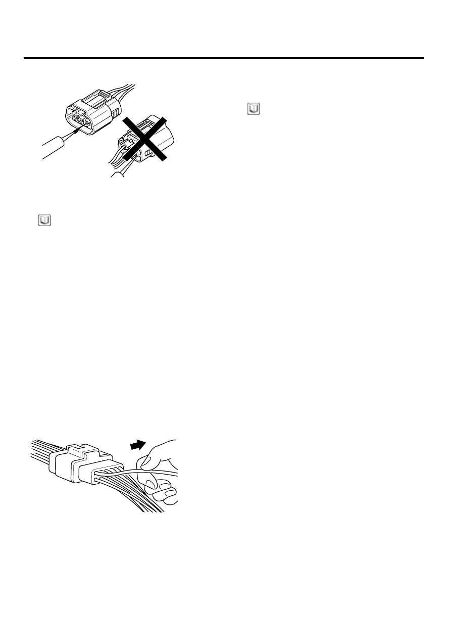
Checking Point for Connector
a.

While the connector is connected:
Hold the connector, check connecting condition
and locking efficiency.

b.

When the connector is disconnected:
Check missed terminal, crimped terminal or bro-
ken core wire by slightly pulling the wire harness.
Visually check for rust, contamination, deforma-
tion and bend.

c.

Check terminal tightening condition:
Insert a spare male terminal into a female ter-
minal, and then check terminal tightening condi-
tions.

d.

Pull lightly on individual wires to ensure that each
wire is secured in the terminal.

BFGE015K

3.

Repair Method of Connector Terminal
a.

Clean the contact points using air gun and/or
shop rag.

NOTE

Never use sand paper when polishing the contact
points, otherwise the contact point may be damaged.

b.

In case of abnormal contact pressure, replace
the female terminal.

WIRE HARNESS INSPECTION PROCEDURE

1.

Before removing the wire harness, check the wire har-
ness position and crimping in order to restore it cor-
rectly.

2.

Check whether the wire harness is twisted, pulled or
loosened.

3.

Check whether the temperature of the wire harness is
abnormally high.

4.

Check whether the wire harness is rotating, moving
or vibrating against the sharp edge of a part.

5.

Check the connection between the wire harness and
any installed part.

6.

If the covering of wire harness is damaged; secure,
repair or replace the harness.

GENERAL

FL -15

ELECTRICAL CIRCUIT INSPECTION PROCEDURE

CHECK OPEN CIRCUIT

1.

Procedures for Open Circuit

• Continuity Check
• Voltage Check

If an open circuit occurs (as seen in [FIG. 1]), it can
be found by performing Step 2 (Continuity Check
Method) or Step 3 (Voltage Check Method) as shown
below.

SENSOR

ECM

(A)

(B)

(C)

1

1

1

1

2

2

2

2

FIG  1

BFGE501A

2.

Continuity Check Method

NOTE

When measuring for resistance, lightly shake the wire
harness above and below or from side to side.

Specification (Resistance)
1

or less

Normal Circuit

1

or Higher

Open Circuit

a.

Disconnect connectors (A), (C) and measure
resistance between connector (A) and (C) as
shown in [FIG. 2].

In [FIG.2.] the measured resistance of line 1 and
2 is higher than 1

and below 1

respectively.

Specifically the open circuit is line 1 (Line 2 is
normal). To find exact break point, check sub line
of line 1 as described in next step.

SENSOR

ECM

(A)

(B)

(C)

1

1

1

1

2

2

2

2

FIG  2

BFGE501B

b.

Disconnect connector (B), and measure for resis-
tance between connector (C) and (B1) and be-
tween (B2) and (A) as shown in [FIG. 3].

In this case the measured resistance between
connector (C) and (B1) is higher than 1

and the

open circuit is between terminal 1 of connector
(C) and terminal 1 of connector (B1).

SENSOR

ECM

(A)

(B2)

(C)

1

1

1

1

2

2

2

2

FIG  3

(B1)

BFGE501C

3.

Voltage Check Method
a.

With each connector still connected, measure the
voltage between the chassis ground and terminal
1 of each connectors (A), (B) and (C) as shown
in [FIG. 4].

The measured voltage of each connector is 5V,
5V and 0V respectively. So the open circuit is
between connector (C) and (B).

FL -16

FUEL SYSTEM

V

SENSOR

ECM

(A)

(B)

(C)

1

1

1

1

2

2

2

2

FIG  4

BFGE501D

CHECK SHORT CIRCUIT

1.

Test Method for Short to Ground Circuit

• Continuity Check with Chassis Ground

If short to ground circuit occurs as shown in [FIG. 5],
the broken point can be found by performing Step 2
(Continuity Check Method with Chassis Ground) as
shown below.

SENSOR

ECM

(A)

(B)

(C)

1

1

1

1

2

2

2

2

FIG  5

BFGE501E

2.

Continuity Check Method (with Chassis Ground)

NOTE

Lightly shake the wire harness above and below, or
from side to side when measuring the resistance.

Specification (Resistance)
1

Ω

or less

Short to Ground Circuit

1M

Ω

or Higher

Normal Circuit

a.

Disconnect connectors (A), (C) and measure for
resistance between connector (A) and Chassis
Ground as shown in [FIG. 6].

The measured resistance of line 1 and 2 in this
example is below 1

and higher than 1M

Ω

re-

spectively. Specifically the short to ground circuit
is line 1 (Line 2 is normal). To find exact broken
point, check the sub line of line 1 as described in
the following step.

SENSOR

ECM

(A)

(B)

(C)

1

1

1

1

2

2

2

2

FIG  6

BFGE501F

b.

Disconnect connector (B), and measure the
resistance between connector (A) and chassis
ground, and between (B1) and chassis ground
as shown in [FIG. 7].

The measured resistance between connector
(B1) and chassis ground is 1

or less.

The

short to ground circuit is between terminal 1 of
connector (C) and terminal 1 of connector (B1).

SENSOR

ECM

(C)

1

1

2

2

(B1)

(B2)

1

1

2

2

(A)

FIG  7

BFGE501G

GENERAL

FL -17

SYMPTOM TROUBLESHOOTING GUIDE TABLE

(SYMPTOM 1) ENGINE DOES NOT START

Possible Cause

• Run out of fuel
• Starter faulty
• Fuel pump hose supply cut
• High pressure leakage
• Fuse out of order
• Drift of the rail pressure sensor not detected
• Cam and Crank signals missing simultaneously
• Battery voltage too low
• Faulty immobilizer
• Electric EGR control valve blocked open
• Fuel pressure regulator valve contaminated,

stuck, jammed

• Rail pressure regulator valve contaminated,

stuck, jammed

• Fuel quality / presence of water

• Inversion of low pressure fuel connections
• Fuel filter not adapted
• Low pressure fuel circuit sealed
• Sealed fuel filter
• Intermittent fault connection
• Air ingress in the low pressure fuel circuit
• Fuel return circuit of the pump sealed
• Engine compression too low
• Leakage at the injector
• Low pressure fuel pump faulty
• High pressure fuel pump faulty
• Injector jammed open
• Bug software or hardware fault not detected
• Glow system faulty

(SYMPTOM 2) ENGIEN STARTS WITH DIFFICULTY OR STARTS AND STALLS

Possible Cause

• Run out of fuel
• Fuel return hose of injector cut
• High pressure leakage
• Fuse faulty
• Air filter sealed
• Alternator or voltage regulator faulty
• The compensation of individual injector not adapted
• Drift of the engine coolant temperature

sensor not detected

• Drift of the rail pressure sensor not detected
• Battery voltage too low
• Electric EGR control valve blocked open
• Fuel pressure regulator valve contaminated,

stuck, jammed

• Rail pressure regulator valve contaminated,

stuck, jammed

• Fuel quality / presence of water

• Inversion of low pressure fuel connections
• Low pressure fuel circuit sealed
• Sealed fuel filter
• Oil level too high/too low
• Catalytic converter sealed or damaged
• Intermittent fault connection
• Air ingress in the low pressure fuel circuit
• Fuel return circuit of the pump sealed
• Glow system faulty
• Engine compression too low
• Fuel return hose of injector sealed
• Carbon deposit on the injector (sealed holes)
• Needle stuck (injection possible over a

certain pressure)

• Gasoline in fuel
• Bug software or hardware fault not detected


Content   ..  349  350  351  352   ..