Hyundai Santa Fe (2006 year). Manual - part 328
ENGINE BLOCK
EMA -23
11) Select the proper connecting rod bearing from
the table below.
CONNECTING ROD
IDENTIFICATION MARK
0(A)
1(B)
2(C)
I(A)
E
(YEL-
LOW)
D
(GREEN)
C
(-)
II(B)
D
(GREEN)
C
(-)
B
(BLACK)
CRANK-
SHAFT
INDEN-
TIFICA-
TION
MARK
III(C)
C
(-)
B
(BLACK)
A
(BLUE)
3.
Check the connecting rod.
1)
When reinstalling, check the cylinder numbers
on the connecting rods and the caps. When in-
stalling a new connecting rod, the notches for
bearing fixing on the connecting rods and caps
should face the same direction.
2)
If one or both edge of the connecting rod thrust
surface is damaged, replace the rod. If the inner
surface of the rod is damaged or rough, also re-
place it.
3)
Using a connecting rod aligner, measure the bent
or torsion of the rod. If the measurement is near
the specification, adjust the rod with a press. If
the rod is bent or twisted excessily, replace it.
Bending : 0.05mm/100mm(0.0020in./3.9370in.)
Torsion : 0.1mm/100mm(0.0039in./3.9370in.)
NOTE
When assembling the rod without a bearing, there
should be no difference.
4.
Check the crankshaft bearing oil clearance.
1)
To check main bearing-to-journal oil clearance,
remove the main bearing caps and bearing
halves.
2)
Clean each main journal and bearing half with a
clean shop tower.
3)
Place one strip of plastigage across each main
journal.
4)
Reinstall the bearings and caps, then torque the
bolts.
Tightening torque
M8 : 15.7Nm(1.6 kgf.m, 11.6lb-ft) + 90
M10 : 29.4 Nm(3.0 kgf.m, 21.7lb-ft)+ 90
NOTE
Tighten the bolts in order.
5)
Remove the cap and bearing again, and measure
the widest part of the plastigage.
Standard oil clearance
0.004~ 0.022mm (0.0002 ~ 0.0009in.)
EDQF075A
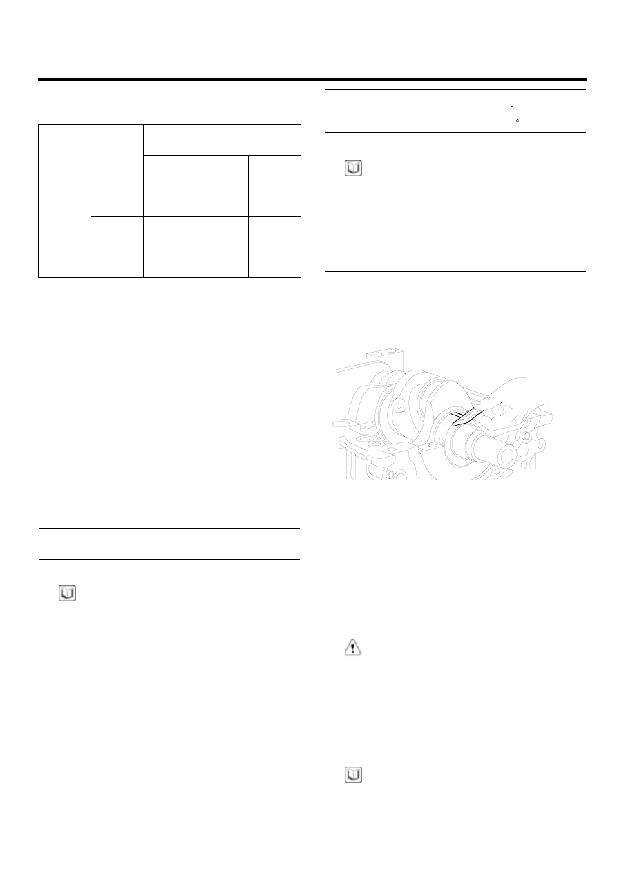
6)
If the plastigage measures too wide or too nar-
row, remove the upper half of the bearing, in-
stall a new, complete bearing with the same color
mark (select the color as shown in the next col-
umn), and recheck the clearance.
CAUTION
Do not file, shim, or scrape the bearings or the
caps to adjust clearance.
7)
If the plastigage shows the clearance is still in-
correct, try the next larger or smaller bearing (the
color listed above or below that one), and check
clearance again.
NOTE
If the proper clearance cannot be obtained by using
the appropriate larger or smaller bearings, replace the
crankshaft and start over.