Hyundai Santa Fe (2006 year). Manual - part 312


  Index      Hyundai     Hyundai Santa Fe - service repair manual 2006 year


Search            


Content   ..  310  311  312  313   ..


Hyundai Santa Fe (2006 year). Manual - part 312


EM -50

ENGINE (D4EB - DIESEL 2.2)

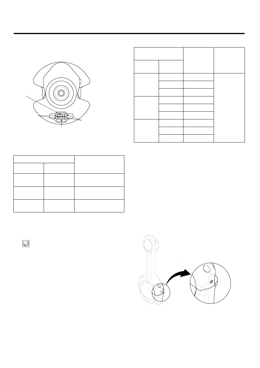
Main Journal Code Locations

2.

The main Journal Codes are stamped on the No.1
web.

Connecting rod
journal code

No. 4 (or 5)
journal
(Drive plate end)

Main journal
code

No. 1 journal
(Pulley end)

LCIF031A

Discrimination of crank shaft

Discrimination

Class

Mark

SIZE (mm)

(Outside diameter of

main journal)

I

A

Ø60

(+0.014 ~ +0.020)

II

B

Ø60

(+0.008 ~ +0.014)

III

C

Ø60

(+0.002 ~ +0.008)

3.

Use the crank bore codes and crank journal codes to
select the appropriate replacement bearings from the
following table.

NOTE

• Color code is on the edge of the bearing. Refer to

the table in the step 6 of the main bearing clear-
ance inspection.

• When using bearing halves of different colors, it

dose not matter which color is used in the top or
bottom.

Installing procedure of bearing

Shaft bore

combination

Shaft

mark

Bore

mark

Bearing

mark

Oil

clearance

A (A)

A (BLUE)

B (B)

B (BLACK)

I (A)

C (C)

C ( - )

A (A)

B (BLACK)

B (B)

C ( - )

II (B)

C (C)

D (GREEN)

A (A)

C ( - )

B (B)

D (GREEN)

III (C)

C (C)

E (YELLOW)

0.024 ~ 0.042

mm

ROD BEARING SELECTION

1.

Inspect each connecting rod for cracks and heat dam-
age.

Connecting Rod Big End Bore Code Locations

2.

Each rod has tolernance range from 0 to 0.018mm
(0.0007in.), in 0.006mm (0.0002in.) increments, de-
pending on the size of its big end bore.

It’s then

stamped with a letter (A, B or C) indicating the range.
You may find any combination of letters in any engine.

If you can’t read the code because of an accumulation
of oil and varnish, do not scrub them with a wire brush
or scraper. Clean them only with solvent or detergent.

LCIF032A

ENGINE BLOCK

EM -51

NOTE

Discrimination connecting rod

Discrimination

Class

Mark

SIZE (mm)

(Inside diameter of

connecting rod big

end bore)

A

A

Ø 53

(0 ~ +0.006)

B

B

Ø 53

(+0.006 ~ +0.012)

C

C

Ø 53

(+0.012 ~ +0.018)

Connecting Rod Journal Code Locations

3.

The connecting Rod Journal Codes are stamped on
the No. 1 web.

Connecting rod journal code locations (letters)

Connecting rod
journal code

No. 4 (or 5)
journal
(Drive plate end)

Main journal
code

No. 1 journal
(Pulley end)

LCIF031A

NOTE

Discrimination of crank shaft pin

Discrimination

Class

Mark

SIZE (mm)

(Outside diameter

of pin)

I

A

Ø50

(+0.020 ~ +0.026)

II

B

Ø50

(+0.014 ~ +0.020)

III

C

Ø50

(+0.008 ~ +0.014)

4.

Use the big end bore codes and rod journal codes
to select appropriate replacement bearings from the
following table.

NOTE

Color code is on the edge of the bearing.
Refer to the table in the step 5 of rod bearing clear-
ance inspection.

Shaft bore combination

Sahft mark

Bore mark

Bearing

mark

Oil

clearance

A (A)

A (BLUE)

B (B)

B (BLACK)

I

C (C)

C (WHITE)

A (A)

B (BLACK)

B (B)

C (WHITE)

II

C (C)

D (GREEN)

A (A)

C (WHITE)

B (B)

D (GREEN)

III

C (C)

E

(YELLOW)

0.024 ~

0.042 mm

PISTON, PIN AND CONNECTING ROD

1.

Apply engine oil to the piston pin snap rings and turn
them in the ring grooves.

NOTE

Take care not to damage the ring grooves.

2.

Remove both snap rings(A) carefully so they do not
go flying or get lost. Wear eye protection.

LCIF033A

EM -52

ENGINE (D4EB - DIESEL 2.2)

3.

Remove the piston pin and the conecting rod assem-
bly.

4.

Measure the diameter of the piston pin.

Piston Pin Diameter
Standard (New)
27.995 ~ 28.000mm (1.1022 ~ 1.1024in.)

ACIE134A

NOTE

Inspect the piston, piston pin and connecting rod
when they are at room temperature.

5.

Set a snap ring in one side of piston pin hole.

6.

Before inserting the piston pin, apply a sufficient
amount of the lubricant oil to the outer surface of the
piston, the inner surface of the piston pin hole and
the small end bore of the connecting rod.

7.

Insert the piston pin(A). Assembly the piston and con-
necting rod with the embossed front marks on the
same side.

A

ACIE133A

NOTE

The front mark of the piston is embossed on the piston
whereas some letters are located on a side surface of
the connecting rod as the front mark.

CAUTION

• Be sure to keep the small end bore, piston

pin hole and piston pin undamaged and un-
scratched when inserting the piston pin.

• Set the snap rings to be sure for contacting

with the groove of the piston pin hole.

ENGINE BLOCK

EM -53

PISTON RING

1.

Using a piston, push a new ring into the cylinder bore.

ACIE137A

2.

Measure the piston ring end-gap(B) with a feeler
gauge :

• If the gap is too small, check to see if you have

the proper rings for your engine.

• If the gap is too large, recheck the cylinder bore

diameter against the wear limits.
If the bore is over the service limit, the cylinder
block must be rebored.

Piston Ring End-Gap
Top ring
Standard (New) : 0.25 ~ 0.40mm (0.0098 ~ 0.0157in.)
Second Ring
Standard (New) : 0.40 ~ 0.60mm (0.0157 ~ 0.0236in.)
Oil Ring
Standard (New) : 0.20 ~ 0.40mm (0.008 ~ 0.016in.)

3.

After installing a new set of rings, measure the ring-to-
groove clearances :

Top Ring Clearance
Standard (New)
0.083 ~ 0.137mm (0.0033 ~ 0.0054in.)

ACIE135A

Second Ring Clearance
Standard (New)
0.065 ~ 0.110mm (0.00256 ~ 0.00433in.)

Oil Ring Clearance
Standard (New)
0.03 ~ 0.07mm (0.00118 ~ 0.00275in.)

ACIE136A


Content   ..  310  311  312  313   ..