Hyundai Santa Fe (2006 year). Manual - part 307


  Index      Hyundai     Hyundai Santa Fe - service repair manual 2006 year


Search            


Content   ..  305  306  307  308   ..


Hyundai Santa Fe (2006 year). Manual - part 307


EM -30

ENGINE (D4EB - DIESEL 2.2)

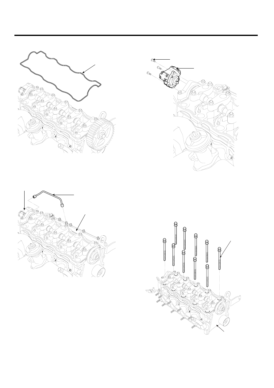
10. Remove the cylinder head cover gasket(A).

A

LCIF018A

11. Remove the metal tube(A) between the fuel pump(B)

and the common rail(C).

B

A

C

ACIE064A

12. Remove the fuel pump(A) after removing the three

bolts(B).

B

A

ACIE065A

13. Remove the exhaust manifold.

14. Remove the intake manifold.

15. Remove the cylinder head bolts(A), then remove the

cylinder head(B).

A

B

ACIE066A

CYLINDER HEAD ASSEMBLY

EM -31

CAUTION

To prevent warpage, unscrew the bolts in sqience
1/3 turn at a time: repeat the sequence until all
bolts are loosened.

CYLINDER HEAD BOLTS LOOSENING SEQUENCE

2                 8               10                 6                4

  3                5                 9                 7                 1

ACIE067A

DISASSEMBLY

E9BF1486

NOTE

• Identify parts as they are removed to ensure re-

installation in original locations.

• Inspect camshafts.

1.

Remove the engine hangers, the knock bushes and
the studs.

2.

Remove the camshaft bearing caps(A).

A

ACIE068A

3.

Remove the camshaft(A) with the oil seal(B).

A

B

ACIE069A

EM -32

ENGINE (D4EB - DIESEL 2.2)

4.

Remove the In/Ex cam followers(A, B).

B

A

D

C

ACIE070A

5.

Remove the lash adjusters(C).

6.

Remove the valve caps(D).

7.

Using an appropriate-sized socket and plastic mal-
let, lightly tap the valve retainer to loosen the valve
retainer locks before installing the valve spring com-
pressor.

NOTE

Identify valves and valve springs as they are removed
so that each item can be reinstalled in its original po-
sition.

8.

Using the SST(09222-27300), compress the valve
spring(A) in order to remove the valve spring retainer
locks(B).

B

A

09222-27300

ACIE071A

9.

Remove the valve stem seals(A).

A

ACIE072A

CYLINDER HEAD ASSEMBLY

EM -33

INSPECTION

E680F0AE

CAMSHAFT

NOTE

Do not rotate the camshaft during inspection.

1.

Put the camshaft(A) and the camshaft bearing
caps(B) on the cylinder head(C), then tighten the
bolts to the specified torque with the following se-
quence below.

Specified torque
26.5 ~ 29.5N.m (2.65 ~ 2.95kgf.m, 20 ~ 22lb-ft)

10    6                 2                 3                 7                11

9     5                 1                 4                  8               12

A

C

B

ACIE073A

2.

Seat the camshaft by pushing it toward the rear of the
cylinder head.

3.

Zero the dial indicator(A) against the end of the
camshaft(B).
Push the camshaft(B) back and forth, and read the
end play.

Camshaft End Play
Standard (New) : 0.05 ~ 0.15mm (0.002 ~ 0.006in.)

B

A

ACIE074A

4.

Remove the bolts, then remove the camshaft bearing
caps from the cylinder head(A).

• Lift the camshaft(B) out of the cylinder head(A),

wipe it clean. Replace the camshaft if any lobes
are pitted, scored, or excessively worn.

• Clean the camshaft bearing surfaces in the cylin-

der head, then set the camshaft back in place.

• Place a plastigauge strip(C) across each journal.

5.

Install the camshaft bearing caps and tighten the bolts
to the specified torque.

6.

Remove the camshaft bearing caps, then measure
the widest portion of the plastigage(C) on each jour-
nal.

Camshaft-to-Camshaft bearing cap oil clearance
Standard (New)
0.040 ~ 0.074mm (0.0020 ~ 0.0029in.)

A

B

C

LCIF020A

7.

Check the cam height wear.

[Standard]
Intake : 34.697mm (1.366in.)
Exhaust : 34.571mm (1.361in.)

ACIE076A


Content   ..  305  306  307  308   ..