Hyundai Santa Fe (2006 year). Manual - part 249


  Index      Hyundai     Hyundai Santa Fe - service repair manual 2006 year


Search            


Content   ..  247  248  249  250   ..


Hyundai Santa Fe (2006 year). Manual - part 249


BR -168

BRAKE SYSTEM

MONITOR ACTUATION TEST

E7DFBFCD

1.

Connect scantool to Data Link Connector(DLC)

2.

Ignition "ON"

Engine "OFF".

3.

Select the "Actuation Test" mode on the scantool.

4.

Inspect opearating status of inlet valve with Actuation Test.

Specification : It’s normal if operating sound is heard.

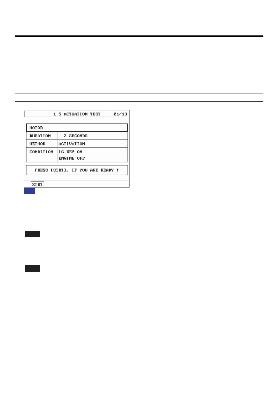
Fig 1)  Test Condition : Ignition "ON" & Engine "OFF"
           Ex) Actuation Test on motor

Fig1

SCMBR6574L

5.

Does a inlet valve operate normally?

YES

Fault is intermittent caused by poor connection in motor circuit or was repaired and HECU memory was not cleared.

Thoroughly check connectors for looseness, poor connection, bending, corrosion, contamination, deterioration, or
damage. Repair or replace as necessary and then go to "Verification Of Vehicle Repair" procedure.

NO

Go to "W/Harness Inspection" procedure.

TERMINAL

CONNECTOR INSPECTION

E60065FA

Refer to DTC C1200.

ABS (ANTI-LOCK BRAKE SYSTEM)

BR -169

POWER SUPPLY CIRCUIT INSPECTION

EDAFB067

1.

Ignition "OFF".

2.

Disconnect HECU connector.

3.

Ignition "ON".

4.

Measure voltage between terminal "2" of the HECU harness connector and chassis ground.

Specification : Approx. B+

V

2. Battery(+)

1

5 6

8 9 10 11 12 13 14 15 16

18

20 21

26 27 28 29 30 31 32 33

35

37 38

2

3

4

*

*

*

* * * *

* * *

* *

*

*

*

*

*

<C281 GSL>

SCMBR6575L

5.

Is the measured voltage within specifications?

YES

Go to "Ground Circuit Inspection" procedure.

NO

Check for damaged harness and open or short to GND between the battery terminal(+) and terminal "2" of the

HECU harness connector. Check for open or blown 40A ABS fuse referring to "Circuit Diagram". Repair as necessary
and then go to "Verification Of vehicle Repair" procedure.

BR -170

BRAKE SYSTEM

GROUND CIRCUIT INSPECTION

E92788A0

1.

Ignition "OFF".

2.

Disconnect HECU connector.

3.

Measure resistance between terminal "1" of the HECU harness connector and chassis ground.

Specification : Approx. below 1

Ω

1. Ground

1

5 6

8 9 10 11 12 13 14 15 16

18

20 21

26 27 28 29 30 31 32 33

35

37 38

2

3

4

*

*

*

* * * *

* * *

* *

*

*

*

*

*

<C281 GSL>

SCMBR6576L

4.

Is the measured resistance within specifications?

YES

Substitute with a known-good HECU and check for proper operation. If problem is corrected, replace HECU and

then go to "Verification Of Vehicle Repair" procedure.

NO

Check for damaged harness and poor connection between terminal "1" of the HECU harness connectorand chas-

sis ground. Repair as necessary and then go to "Verification Of vehicle Repair" procedure.

VERIFICATION OF VEHICLE REPAIR

E68792E0

Refer to DTC C1101.

ABS (ANTI-LOCK BRAKE SYSTEM)

BR -171

ANTI-LOCK BRAKING SYSTEM
CONTROL MODULE

COMPONENTS

EDD0BBD5

1. HCU assembly
2. ECU assembly

1

2

5.9 ~ 9.8 (0.6 ~ 1.0, 4.3 ~ 7.2)

TORQUE : Nm (Kgf.m, lb-ft)

SCMBR6577L


Content   ..  247  248  249  250   ..