Hyundai Santa Fe (2006 year). Manual - part 58
AT -184
AUTOMATIC TRANSAXLE (F4A51)
INSPECTION
EFB6BAFB
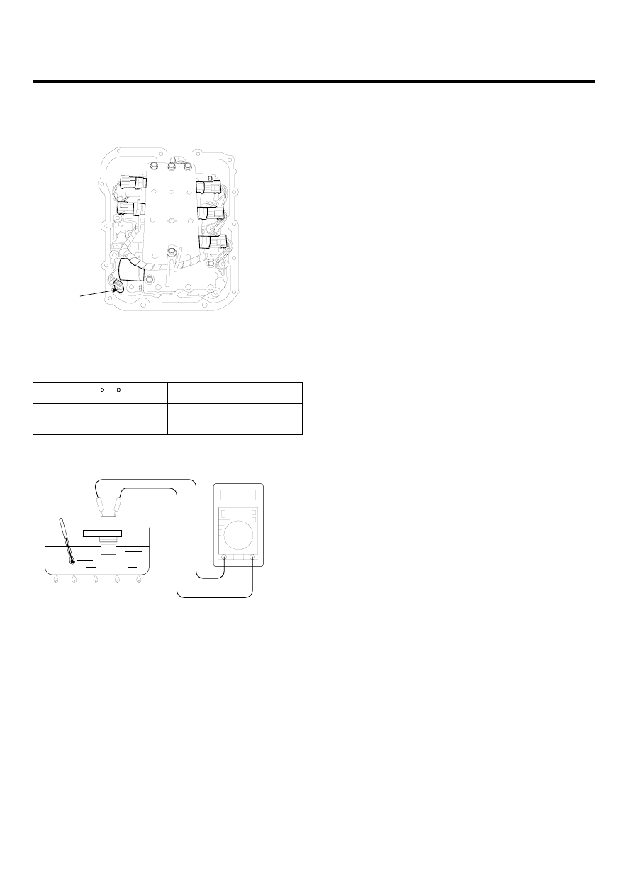
1.
Remove the oil temperature sensor(A).
A
EKRF009D
2.
Measure the resistance between the terminal 1 and 2
of the sensor connector.
Temp.[ C( F)]
Resistance(KΩ )
0(32)
100(212)
18.6
0.63
EKRF009E
3.
If the value is out of the specfication, replace the oil
temperature sensor.