Hyundai Santa Fe (2006 year). Manual - part 39
 

  Index      Hyundai     Hyundai Santa Fe - service repair manual 2006 year


Search            


Content   ..  37  38  39  40   ..


Hyundai Santa Fe (2006 year). Manual - part 39


AT -108

AUTOMATIC TRANSAXLE (F4A51)

2.

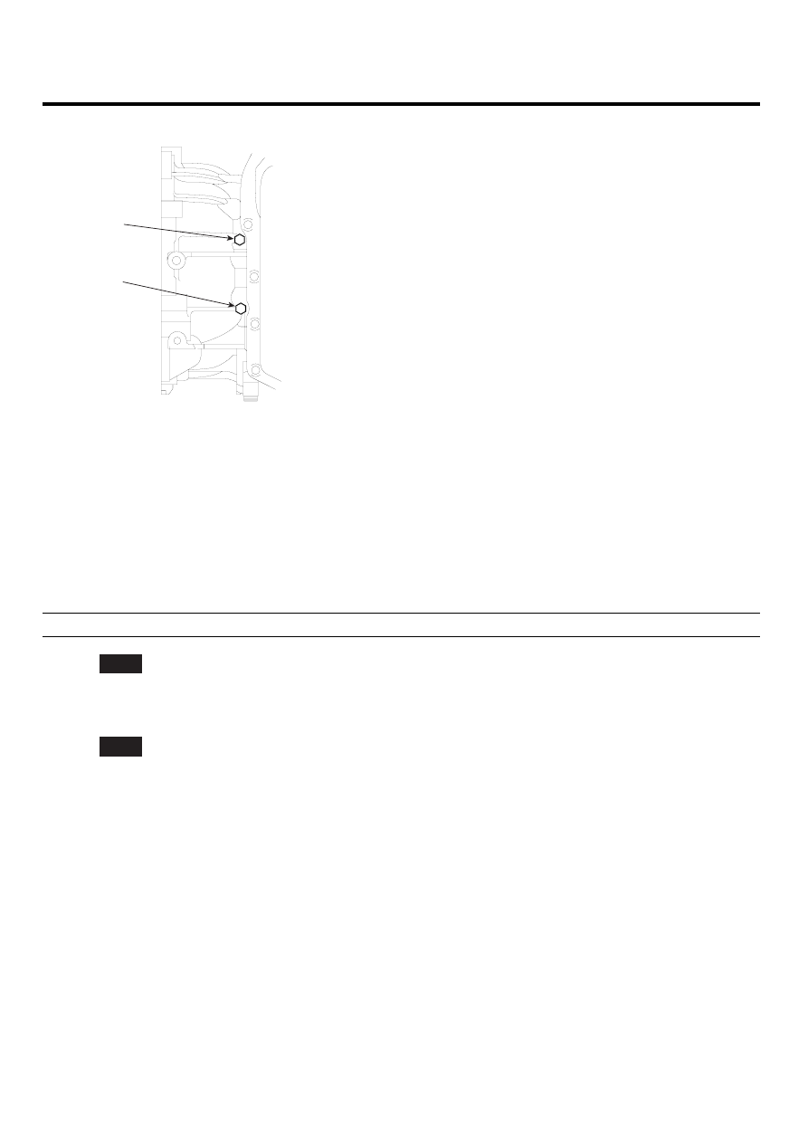
CHECK OIL PRESSURE

DA

DR

KKCF212B

1)

Connect oil pressure gauge to "DR" ports.

2)

Ignition "ON" & Engine "OFF".

3)

After connecting scantool and monitor the "TCC SOLENIOD VALVE DUTY" parameter on the scantool data list.

4)

Select 1st gear and accelerate Engine speed to 2500 rpm.

5)

Measure oil pressure.

6)

Is oil pressure value within specification?

Specification : approx. 598.2034KPa(6.1kg/cm²)

YES

▶ Repair TORQUE CONVERTER CLUTCH(REPLACE Torque Converter ) as necessary and go to "Verification
of vehicle repair" procedure.

NO

▶ Replace A/T assembly (possible to BODY CONTROL VALVE faulty) as necessary and Go to "Verification of
vehicle Repair" procedure.

VERIFICATION OF VEHICLE REPAIR

E4AD7DD3

Refer to DTC P0741.

AUTOMATIC TRANSAXLE SYSTEM

AT -109

DTC P0743 TORQUE CONVERTER CLUTCH CIRCUIT - ELECTRICAL

COMPONENT LOCATION

EA07A4D4

Fluid temperature
sensor

UD
Solenoid
valve

2ND
Solenoid
valve

Damper clutch 
Solenoid
valve

OD 
Solenoid
valve

LR
Solenoid
valve

VFS
Solenoid
valve

EKRF410A

GENERAL DESCRIPTION

E406CFBC

The PCM/TCM controls the locking and unlocking of the Torque Converter Clutch (or Damper Clutch), to the input shaft
of the transmission, by appling hydraulic pressure. The main purpose of T/C clutch control is to save fuel by decreasing
the hydraulic load inside the T/C. The PCM/TCM outputs duty pulses to control the Damper Clutch Control Solenoid
Valve(DCCSV) and hydraulic pressure is applied to the DC according to the DCC duty ratio value. When the duty ratio
is high, high pressure is applied and the Damper Clutch is locked. The normal operating range of the Damper Clutch
Control duty ratio value is from 30%(unlocked) to 85%(locked).

DTC DESCRIPTION

E172CCCE

The PCM/TCM checks the Damper Clutch Control Signal by monitoring the feedback signal from the solenoid valve drive
circuit. If an unexpected signal is monitored (for example, high voltage is detected when low voltage is expected, or low
voltage is detected when high voltage is expected) the PCM/TCM judges that DCCSV circuit is malfunctioning and sets
this code.

DTC DETECTING CONDITION

EFAE4AC1

Item

Detecting Condition

Possible cause

DTC Strategy

• Check voltage range

Enable Conditions

• 16V > Voltage Battery >11V
• In gear state(no gear shifting) 500msec is

passed from turn on the relay

• A/T Relay = ON
• Engine state = RUN

Threshold value

• Feedback voltage from DCC control solenoid>

vb-2V and DCC control duty is 100%

Diagnostic Time

• More than 2 seconds

Fail Safe

• Locked in 3rd gear.(Control relay off)

※ TORQUE CON-
VERTER(DAMPER) CLUTCH
: TCC

• Open or short in circuit
• Faulty TCC SOLENOID

VALVE

• Faulty PCM/TCM

AT -110

AUTOMATIC TRANSAXLE (F4A51)

SPECIFICATION

E7EDFA7E

Solenoid Valve for Pressure Control

• Sensor type : Normal open 3-way
• Operating temperature : -22~266 F(-30 C~130 C)
• Frequency :

-

LR, 2ND, UD, OD, RED : 61.27Hz (at the ATF temp. -20 C above)

-

DCC : 30.64Hz
※ KM series : 35Hz

• Internal resistance :

-

2.7~3.4Ω (68 F or 20 C)

• Surge voltage : 56 V

SIGNAL WAVEFORM

E224E54A

FIG.1)

FIG.1) : Operating of "DCCSV"

EKBF115A

MONITOR SCANTOOL DATA

EDBDCD5A

1.

Connect scantool to data link connector(DLC)

2.

Engine "ON".

3.

Monitor the "TCC SOL. VALVE" parameter on the scantool

4.

Select "D RANGE" and Operate "TCC SOLENOID DUTY" more than 40%.

AUTOMATIC TRANSAXLE SYSTEM

AT -111

FIG.1)

FIG.2)

FIG. 1) P,N 
FIG. 2) "R"
FIG. 3) "D 1st" gear
FIG. 4) "2nd" gear
FIG. 5) "3rd" gear
FIG. 6) "4th" gear
FIG. 7) "5th" gear

FIG.3)

FIG.4)

FIG.5)

FIG.6)

FIG.7)

LLLG114A


Content   ..  37  38  39  40   ..