Hyundai: Engine D4FA. Manual - part 135
DIESEL CONTROL SYSTEM
FLA -411
DTC P1634 AUXILIARY HEATER MALFUNCTION
COMPONENT LOCATION
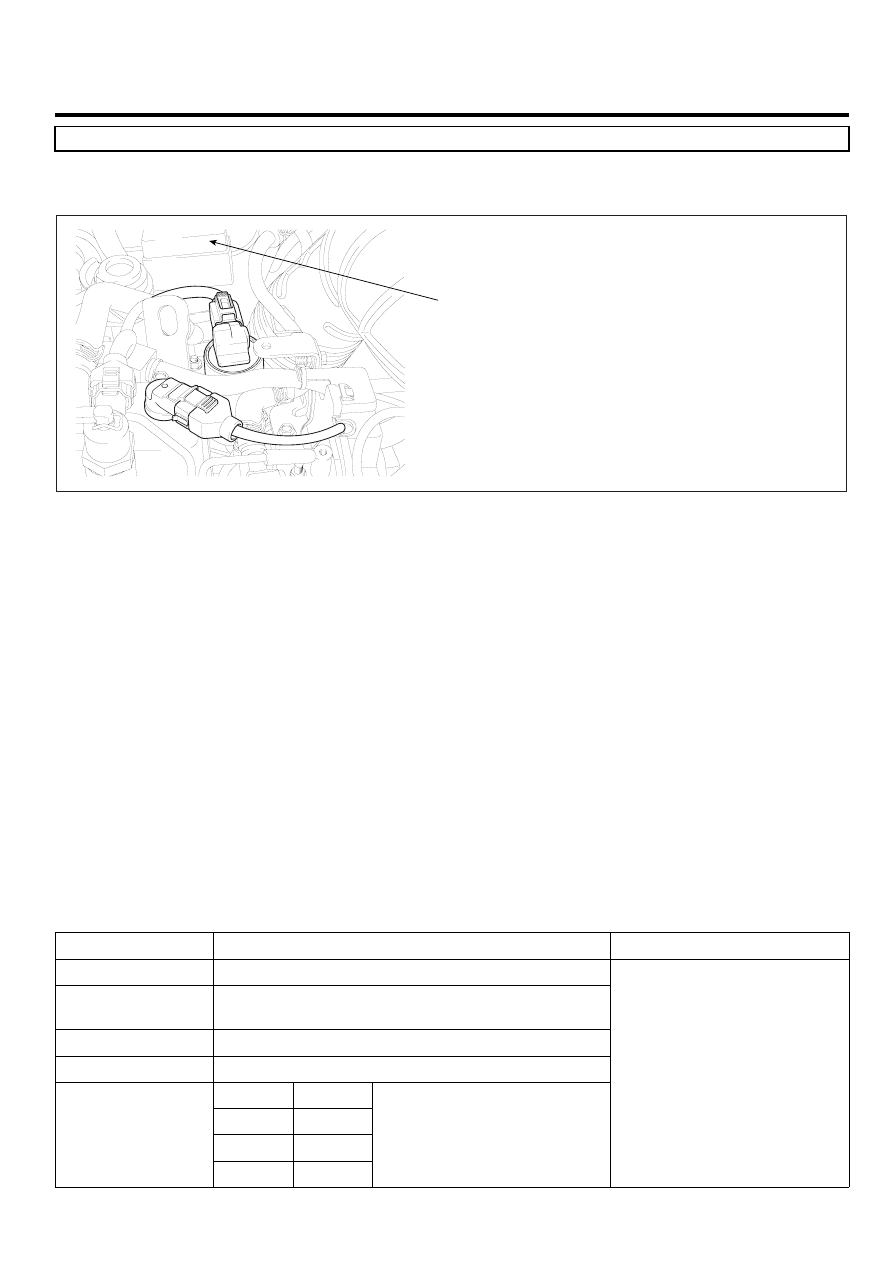
E56FA5A1
Aux. heater relay
EGNG013I
GENERAL DESCRIPTION
E9A6BA6F
Because thermal efficiency of electronically controlled diesel engine is higher than that of gasoline engine, heat loss to
cylinder wall is lower. This enables electronically controlled diesel engine to generate high power and have high fuel
efficiency. However in other point of view, due to low engine coolant temperature, heating efficiency lowered then, driver
is unsatisfied with the heating. To cope with this situation, PTC heater is installed in coolant line and it raises heating
efficiency and raise coolant temperature.ECM activates heater relay 1 and 2 when engine coolant temperature is below
70℃ and engine speed is above 700RPM.
※ Heater relay operation inhibited condition : engine coolant temperature above 70℃, engine speed below 700RPM(to
prevent battery discharge)
DTC DESCRIPTION
E152D41E
P1634 is set when excessive current or "0"A is detected in heater relay control circuit for more than 1.0 sec. at heater
relay operating condition. This code is due to 1)open or 2)short to battery or ground in heater relay control circuit or
3)component problem.
DTC DETECTING CONDITION
EAFFDBB9
Item
Detecting Condition
Possible Cause
DTC Strategy
• Voltage monitoring
Enable Conditions
• IG KEY "ON" (monitoring only performed at
relay operating condition)
ThresholdValue
• Short to battery
DiagnosticTime
• 1.0 sec.
Fuel Cut
NO
EGR Off
NO
Fuel Limit
NO
Fail Safe
MIL
NO
• PTC heater relay #1control
circuit
• Heater relay component