Hyundai: Engine D4FA. Manual - part 25
ENGINE BLOCK
EMA -69
ECKD001G
If the clearance is greater than maximum, replace the
piston.
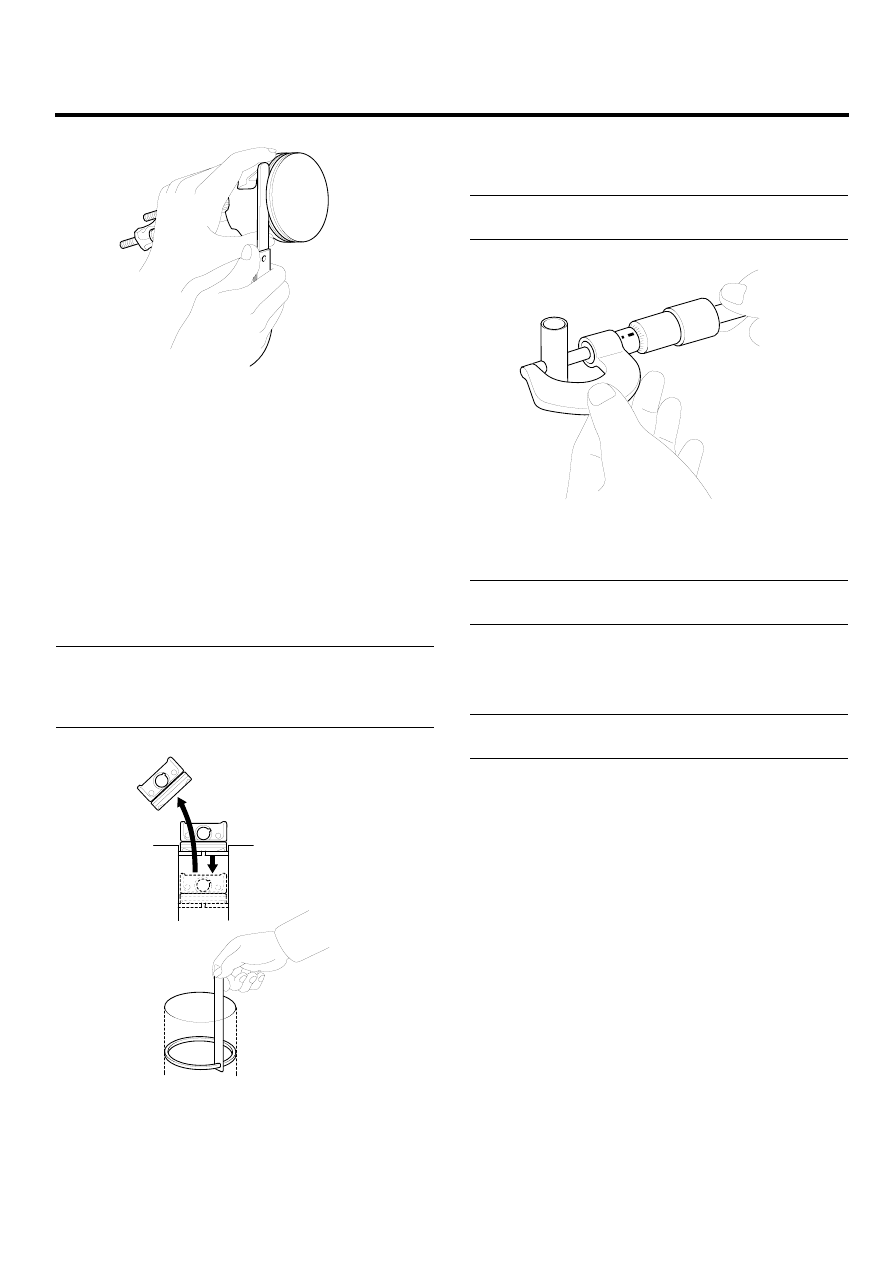
5.
Inspect the piston ring end gap.
To measure the piston ring end gap, insert a piston
ring into the cylinder bore. Position the ring at right
angles to the cylinder wall by gently pressing it down
with a piston. Measure the gap with a feeler gauge. If
the gap exceeds the service limit, replace the piston
rings. If the gap is too large, recheck the cylinder bore
inner diameter. If the bore is over the service limit, the
cylinder block must be rebored. (Refer to EMA-67)
Piston ring end gap
No.1 : 0.20 ~ 0.35mm (0.0079 ~ 0.0138in)
No.2 : 0.35 ~ 0.50mm (0.0138 ~ 0.0197in)
Oil ring : 0.20 ~ 0.40mm(0.0079 ~ 0.0157in)
ECKD001K
PISTON PINS
1.
Measure the outer diameter of piston pin.
Piston pin diameter :
27.995 ~ 28.000mm (1.1022 ~ 1.1024in)
ECKD001Z
2.
Measure the piston pin-to-piston clearance.
Piston pin-to-piston clearance :
0.004 ~ 0.015mm (0.0002 ~ 0.0006in)
3.
Check the difference between the piston pin outer di-
ameter and the connecting rod small end inner diam-
eter.
Piston pin-to-connecting rod interference :
0.022 ~ 0.039mm (0.0009 ~ 0.0015in)