Hummer H3. Manual - part 1031


  Index      Hummer     Hummer H3 - service repair manual 2006-2009 year


Search            


Content   ..  1029  1030  1031  1032   ..


Hummer H3. Manual - part 1031
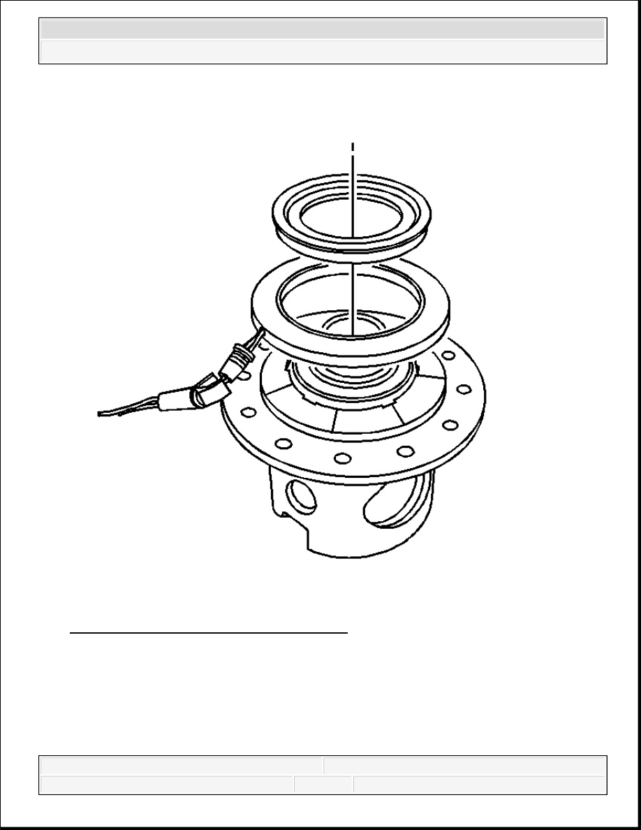


Fig. 167: View Of Differential Bearing Race 
Courtesy of GENERAL MOTORS CORP. 

15. Install the locking differential coil assembly.  

16. Install the differential bearing race. 


2007 Hummer H3 

2007 Driveline/Axle Rear Drive Axle - H3


Fig. 168: Identifying Differential Bearing Retainer 
Courtesy of GENERAL MOTORS CORP. 

17. Install the differential bearing retainer by performing the following steps: 

1. Install the differential bearing retainer.  

2. With the aid of an assistant, push the differential bearing race down towards the 

IMPORTANT: The differential bearing race must be compressed in order to 

install the differential bearing retainer.


2007 Hummer H3 

2007 Driveline/Axle Rear Drive Axle - H3


differential case in order to compress the differential bearing retainer and differential 
coil assembly against the locking differential coil plate.  

3. Install the differential bearing retainer. 

Ensure the differential bearing retainer is evenly and fully seated in the differential 
bearing retainer slot before releasing the differential bearing race. 

18. Install the ring gear. Refer to Drive Pinion and Ring Gear Replacement.  

19. Install the differential side bearings. Refer to Differential Side Bearings Replacement.  

DESCRIPTION AND OPERATION 

LOCKING DIFFERENTIAL DESCRIPTION AND OPERATION 

The electronic locking differential consists of the following components: 


Differential Bearing Retainer Race  


Differential Bearing Race  


Differential Bearing Assembly  


Locking Differential Coil Assembly  


Locking Differential Coil Plate  


Locking Differential Ball Bearing Plate - Outboard  


Locking Differential Ball Bearing Assembly  


Locking Differential Ball Bearing Plate - Inboard  


Locking Differential Clutch Spring  


Locking Differential Clutch Spring Retainer  


Differential Carrier Lock Pins  


Differential Case  


Differential Pinion Gears and Thrust Washers  


Locking Differential Side Gear and Thrust Washer  


Differential Side Gear and Thrust Washer  

The electronic locking differential is a combination of an open differential and an electrically 
energized coil assembly. When the coil is not energized, the differential operates in the same 
manner as an open differential. The locking differential coil assembly is located on the left side of 
the differential case. The locking differential coil is held stationary within the differential case 
housing through the lock tab on the coil and the hold down lock that attaches to the differential 


2007 Hummer H3 

2007 Driveline/Axle Rear Drive Axle - H3


bearing cap. The remainder of the locking components: the locking differential coil plate, the 
locking differential ball bearing plates, the clutch springs and the lock pins are located within the 
differential case and rotate at the same speed as the differential case. The locking function of the 
differential is accomplished by a combination of vehicle and user inputs. In order to the 
differential coil to energize, the vehicle must be operating under the following conditions: 


The transfer case indicator switch indicates 4 LO.  


The vehicle's speed must be less than 4.8 km/h (3 mph).  


The differential lock switch is turned ON.  


The left to right rear wheel speed difference is less than 50 RPM.  

Once the above conditions are met, the automatic transfer case shift control module sends a signal 
to energize the coil. The energized coil creates a magnetic field that allows the outboard locking 
differential ball bearing plate to rotate at a slower speed than inboard locking differential ball 
bearing plate and the differential case. The difference in the 2 speeds causes the ball bearings that 
are between the outboard and the inboard ball bearing plate to move along their respective ramps 
and separate the 2 ball bearing plates. The separation increases the width of the plates and allows 
the differential lock pins to be pushed through the differential case towards the locking 
differential side gear. The locking differential side gear has 6 notches that accept the differential 
lock pins. Once the differential lock pins are engaged, the locking differential side gear can no 
longer rotate independently of the differential case. Since the locking differential side gear is now 
apart of the differential case and turning at the same speed as the ring gear, the pinion gears that 
are perpendicular to the locking differential side gear, cannot rotate within the differential case. 
This causes the bell-side differential side gear to rotate at the same speed as the locking 
differential side gear. The driving force generated by the ring gear, is transmitted through the 
locking differential side gear, through the pinion gears, to the bell-side differential side gear. The 
axle shafts, which are splined to each side gear, receive the force and rotate together at the same 
speed along with the differential case and ring gear. The will remain the locked position until the 
vehicle's speed exceeds 32 km/h (20 mph) or the operator turns OFF the differential lock switch 
or the transfer case is shifted into 4 HI, 2 HI or NEUTRAL. The locking differential coil will de-
energize and the differential will function as an open differential. 

REAR DRIVE AXLE DESCRIPTION AND OPERATION 

The rear axle for this vehicle consist of the following components: 


Differential Carrier Housing  


Differential Case Assembly (Open or Locking)  


Ring Gear and Drive Pinion Shaft  


2007 Hummer H3 

2007 Driveline/Axle Rear Drive Axle - H3


Content   ..  1029  1030  1031  1032   ..