Hummer H2. Manual - part 979


  Index      Hummer     Hummer H2 - service repair manual 2004 year


Search            


Content   ..  977  978  979  980   ..


Hummer H2. Manual - part 979


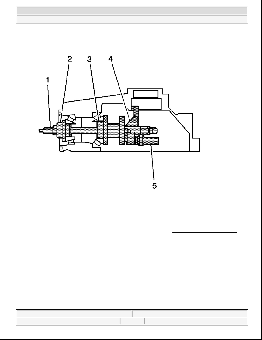
Fig. 110: Assembling J 29763 To J 36601-3 & J 36601-7 
Courtesy of GENERAL MOTORS CORP. 

2. Assemble the J 29763 (5) to the J 36601-3 (4) and J 36601-7 (1). See Special Tools and Equipment .  

3. Assemble the J 21777-8 (3) onto the J 36601-7 (1).  

4. Install the pinion bearings and hold them in place.  

5. Insert the J 36601-7 (1) with the J 21777-8 (3) through the pinion bearings.  

6. Install the J 36601-5 (2), the washer, and the nut to the J 36601-7 (1).  

7. While holding the J 36601-3 (4) stationary, install an inch-pound torque wrench on the nut and tighten the 

nut until a rotating torque of 1.1-2.3 N.m (10-20 lb in) is obtained. 

Rotate the assembly several times in both directions in order to seat the pinion bearings. 

8. Check the rotating torque of the assembly. If the torque is less than 1.0 N.m (10 lb in), tighten the nut on 

the J 36601-7 until a rotating torque of 1.1-2.3 N.m (10-20 lb in) is obtained. 


2004 Hummer H2 

2004 DRIVELINE/AXLE Front Drive Axle - Hummer H2


Fig. 111: Adjusting J 29763 To Differential Bearing Bore 
Courtesy of GENERAL MOTORS CORP. 

9. Adjust the J 29763 (2) to the differential bearing bore by doing the following: 

1. Loosen the lock nut on the J 29763 . See Special Tools and Equipment .  

2. Place the contact pad of the J 36601 on the differential side bearing bore. See Special Tools and 

Equipment .  

3. With the contact pad of the J 36601 touching the differential side bearing bore, push down on the 

29763 until the needle of the J 29763 has turned 3/4 of a turn clockwise. See Special Tools and 
Equipment
 .  

4. Tighten the lock nut of the J 29763 . See Special Tools and Equipment .  

IMPORTANT: The left side differential bearing adjuster assembly must be removed prior 

to placing the J 36601-3 in the differential side bearing bore.


2004 Hummer H2 

2004 DRIVELINE/AXLE Front Drive Axle - Hummer H2


10. Rotate the J 36601 (1) back and forth until the needle of the J 29763 (2) indicates the lowest point in the 

differential side bearing bore. See Special Tools and Equipment .  

11. At the lowest point of deflection, move the housing of the J 29763 until the needle indicates ZERO. See 

Special Tools and Equipment .  

12. Move the J 36601 back and forth again to verify the zero setting. See Special Tools and Equipment . 

Adjust the housing of the J 29763 as necessary to set the needle to ZERO. See Special Tools and 
Equipment
 . 

Fig. 112: Grasping J 36601 By Flats & Moving J 36601 Out Of Differential Side Bearing Bore 
Courtesy of GENERAL MOTORS CORP. 

13. After the ZERO setting is obtained and verified, grasp the J 36601 (1) by the flats and move the J 36601 

out of the differential side bearing bore. See Special Tools and Equipment .  

14. The value indicated on the J 29763 (2) is the thickness of the shim needed in order to set the depth of the 

pinion. See Special Tools and Equipment .  

15. Select the shim that indicates the proper thickness. Measure the shim with a micrometer in order to verify 

that the thickness is correct.  


2004 Hummer H2 

2004 DRIVELINE/AXLE Front Drive Axle - Hummer H2


16. Remove the pinion depth setting tools.  

17. Remove the pinion bearings.  

18. Install the pinion shim between the pinion and the inner pinion bearing. Refer to Differential Carrier 

Assembly - Assemble .  

DIFFERENTIAL CARRIER ASSEMBLY - ASSEMBLE 

Tools Required 

z

J 36366 Pinion Oil Seal Installer. See Special Tools and Equipment .  

z

J 36599-A Side Bearing Nut Wrench. See Special Tools and Equipment .  

z

J 36603 Side Bearing Cup Installer. See Special Tools and Equipment .  

z

J 36609 Axle Tube Bearing Installer. See Special Tools and Equipment .  

z

J 36614 Inner Pinion Bearing Installer. See Special Tools and Equipment .  

z

J 36615 Side Bearing Nut Wrench. See Special Tools and Equipment .  

z

J 8092 Universal Driver Handle - 3/4 in - 10. See Special Tools and Equipment .  

z

J 8614-01 Flange and Pulley Holding Tool. See Special Tools and Equipment .  

1. Install the pinion bearing cups into the differential carrier assembly. Refer to Pinion Bearing Cup 

Installation .  

2. Install the selective shim between the inner pinion bearing and the shoulder of the pinion gear. 


2004 Hummer H2 

2004 DRIVELINE/AXLE Front Drive Axle - Hummer H2


Content   ..  977  978  979  980   ..