Hummer H2. Manual - part 693


  Index      Hummer     Hummer H2 - service repair manual 2004 year


Search            


Content   ..  691  692  693  694   ..


Hummer H2. Manual - part 693


Rear Window Defogger Grid Terminal Identification - C1 

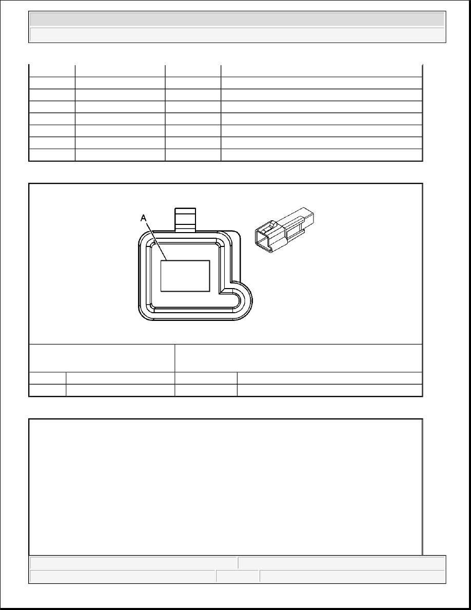
Rear Window Defogger Grid Terminal Identification - C2 

6

D-GN/WH

636

Ambient Air Temperature Sensor Signal

7

BK/WH

1704

Low Reference

8

BK

1050

Ground

9

L-GN

24

Backup Lamp Supply Voltage

10-12

-

-

Not Used

13

BN

341

Ignition 3 Voltage

14-15

-

-

Not Used

16

PK

1691

Automatic Day/Night Mirror Low Reference

Connector Part Information

z

12059885  

z

1-Way M Metri-Pack 480 Series (BK)  

Pin

Wire Color

Circuit No.

Function

A

PU

293

Rear Defog Element Supply Voltage


2004 Hummer H2 

2004 ACCESSORIES & EQUIPMENT Stationary Windows - Hummer H2


DIAGNOSTIC INFORMATION AND PROCEDURES 

DIAGNOSTIC STARTING POINT - STATIONARY WINDOWS 

For the inside rearview mirror with the automatic day-night feature, begin the diagnosis by reviewing the 
system Description and Operation. Reviewing the Description and Operation information will help you 
determine the correct symptom diagnostic procedure when a malfunction exists. Reviewing the Description and 
Operation information will also help you determine if the condition described by the customer is normal 
operation. Refer to Symptoms - Stationary Windows in order to identify the correct procedure for diagnosing 
the system and where the procedure is located. 

For the rear window defogger, begin the diagnosis with the Diagnostic System Check - Defogger . The 
Diagnostic System Check will provide the following information: 

z

The identification of the control modules which command the system  

z

The ability of the control modules to communicate through the serial data circuit  

z

The identification of any stored diagnostic trouble codes (DTCs) and their status  

The use of the Diagnostic System Check will identify the correct procedure for diagnosing the system and 
where the procedure is located. 

DIAGNOSTIC SYSTEM CHECK - DEFOGGER 

Test Description 

Connector Part Information

z

12059885  

z

1-Way M Metri-Pack 480 Series (BK)  

Pin

Wire Color

Circuit No.

Function

A

BK

1450

Ground


2004 Hummer H2 

2004 ACCESSORIES & EQUIPMENT Stationary Windows - Hummer H2


The numbers below refer to the step numbers on the diagnostic table.

2: Lack of communication may be due to a partial malfunction of the class 2 serial data circuit. The 
specified procedure will determine the particular condition.  

4: The Symptom Table will determine the correct diagnostic procedure to use.  

5: The presence of DTCs which begin with "U" indicate some other module is not communicating. The 
specified procedure will compile all the available information before tests are performed.  

Diagnostic System Check - Defogger 

Step

Action

Yes

No

1

Install a scan tool. 
Does the scan tool power up?

Go to Step 2

Go to Scan Tool Does 

Not Power Up in Data 

Link Communications

2

1. Turn ON the ignition, with the engine OFF.  

2. Attempt to establish communication with 

the following: 

z

HVAC Control Module  

z

Body Control Module (BCM)  

Does the scan tool communicate with the 
modules?

Go to Step 3

Go to Scan Tool Does 

Not Communicate 

with Class 2 Device in 

Data Link 

Communications

3

1. Access the Class 2 Power Mode in the 

Diagnostic Circuit Check on the scan tool.  

2. Rotate the ignition switch through all 

positions while observing the Class 2 Power 
Mode on the Scan Tool. Refer to the Serial 
Data Power Mode table within the Body 
Control System Description and 
Operation
 in Body Control System, for a 
list of the power mode states that correspond 
to each ignition switch position.  

Does the Class 2 Power Mode parameter reading 
match the ignition switch position for all the 
selected positions?

IMPORTANT:

The engine may start during the following step. 
Turn OFF the engine as soon as you have 
observed the Crank power mode.

Go to Step 4

Go to Power Mode 

Mismatch in Body 

Control System

4

Select the display DTCs function on the scan tool 
for the following modules. 

z

HVAC Control Module.  


2004 Hummer H2 

2004 ACCESSORIES & EQUIPMENT Stationary Windows - Hummer H2


SCAN TOOL OUTPUT CONTROLS 

Body Control Module (BCM) 

SCAN TOOL DATA LIST 

Body Control Module (BCM) 

SCAN TOOL DATA DEFINITIONS 

Body Control Module (BCM) 

Rear Defog Relay  

The scan tool displays On or Off. When the BCM energizes the RR DEFOG relay, the scan tool will 
display On. When the BCM de-energizes the RR DEFOG relay, the scan tool will display Off. 

DIAGNOSTIC TROUBLE CODE (DTC) LIST 

Diagnostic Trouble Code (DTC) List 

DTC B0283 

z

BCM  

 
Does the scan tool display any DTCs?

Go to Step 5

Go to Symptoms - 

Stationary Windows

5

Does the scan tool display DTCs that begin with 
"U"?

Go to Diagnostic 

Trouble Code (DTC) 

List in Data Link 

Communications

Go to Step 6

6

Does the scan tool display DTC B1000 or B1440?

Go to Diagnostic 

Trouble Code (DTC) 

List in Body Control 

System

Go to Diagnostic 

Trouble Code (DTC) 

List

Scan Tool 

Output Control

Additional Menu 

Selection(s)

Description

Rear Defogger

-

The BCM actuates the rear window defogger relay when you 
select ON. The rear window defogger grid should become warm.

Scan Tool Parameter

Data List

Units Displayed

Typical Data Value

Ignition On/Engine Off

Rear Defog Relay

Outputs

On/Off

Off

DTC

Diagnostic Procedure

Module(s)

B0283

DTC B0283

BCM


2004 Hummer H2 

2004 ACCESSORIES & EQUIPMENT Stationary Windows - Hummer H2


Content   ..  691  692  693  694   ..