Hummer H2. Manual - part 306
Turn Signal/Multi-Function Switch Terminal Identification - C3
Underhood Terminal Identification Lamp (If Equipped)
z
8-Way F Metri-Pack 150 Series (BK)
Pin
Wire Color
Circuit No.
Function
A
L-GN
1427
Right Turn Signal Switch Signal
B
PK
639
Ignition 1 Voltage
C
D-GN
1428
Left Turn Signal Switch Signal
D-F
-
-
Not Used
G
BK/YE
28
Horn Relay Control
H
WH
111
Hazard Switch Signal
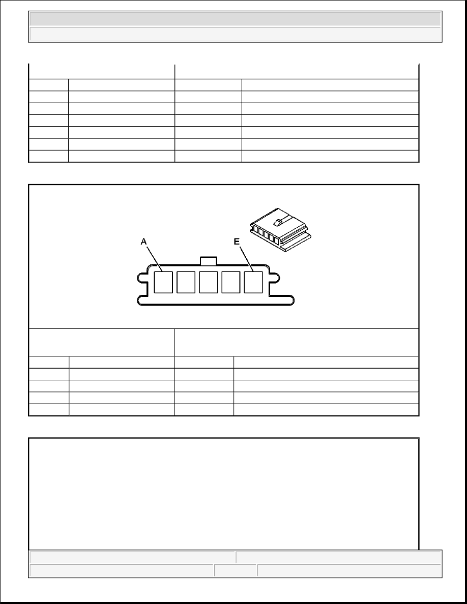
Connector Part Information
z
12059800
z
5-Way F Metri-Pack 150 Series (BK)
Pin
Wire Color
Circuit No.
Function
A
TN
1851
Ground
B
YE/BK
307
Headlamp Switch Flash to Pass Signal
C
L-GN
11
Headlamp Dimmer Switch Signal
D-E
-
-
Not Used
2004 Hummer H2
2004 ACCESSORIES & EQUIPMENT Lighting Systems - Hummer H2