Hummer H2. Manual - part 2230


  Index      Hummer     Hummer H2 - service repair manual 2004 year


Search            


Content   ..  2228  2229  2230  2231   ..


Hummer H2. Manual - part 2230


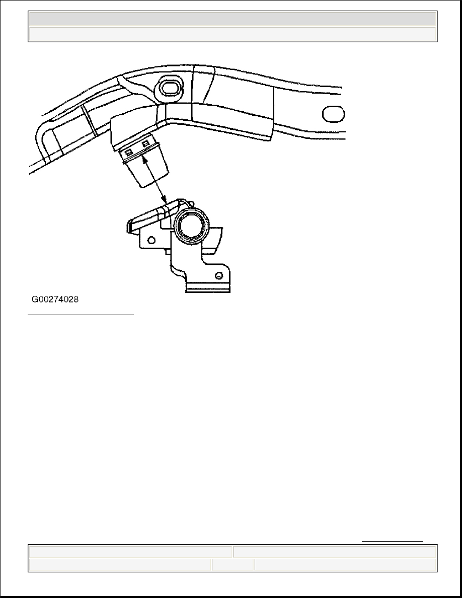
Fig. 3: Measuring D Height 
Courtesy of GENERAL MOTORS CORP. 

ADJUSTMENTS 

FRONT CASTER & CAMBER ADJUSTMENT 

1. Caster is relative to frame, the caster values must be compensated for the measured frame angle by using 

a digital protractor or equivalent on a flat portion of the frame in front of the rear tire.  

2. Frame angle is positive when higher in the rear. Measure both sides of the frame and take an average 

from those measurements. Then add the average frame angle to the caster reading when making 
adjustments.  

3. Frame angle is negative when lower in the rear. Measure both sides of the frame and take an average from 

the measurements. Then subtract the average frame angle from the caster reading when making 
adjustments.  

4. The caster and camber adjustments are made by rotating the offset cam bolt and the cam in the slotted 

frame bracket in order to reposition the control arm 

NOTE:

Before adjusting the caster and camber angles, jounce the front bumper 
three times to allow the vehicle to return to normal height. Measure and 
adjust the caster and the camber with the vehicle at curb height. The front 
suspension Z dimension is indicated in Trim Heights. See TRIM HEIGHT . 


2004 Hummer H2 

2003-04 WHEEL ALIGNMENT Specifications & Procedures - Hummer - H2


5. For an accurate reading, do not push or pull on the tires during the alignment process.  

6. Determine the caster angle (2). Be sure to compensate for frame angle where required. See Fig. 4 .  

7. Determine the positive camber (2) or negative camber (3) angle. See Fig. 5 .  

8. Remove the pinned adjusting cam insert. Do not reinstall the cam insert.  

9. Loosen the upper control arm cam adjustment bolts. See Fig. 6  

10. Adjust the caster and the camber angle by turning the cam bolts until the specifications have been met. 

When the adjustments are complete, hold the cam bolt head in order to ensure the cam bolt position does 
not change while tightening the nut. Tighten cam nuts to specification. See TORQUE 
SPECIFICATIONS 
.  

11. Verify that the caster and the camber are still within specifications. See WHEEL ALIGNMENT 

SPECIFICATIONS . When the caster and camber are within specifications, adjust the toe. See FRONT 
TOE ADJUSTMENT 
.  

Fig. 4: Checking Caster 
Courtesy of GENERAL MOTORS CORP.


2004 Hummer H2 

2003-04 WHEEL ALIGNMENT Specifications & Procedures - Hummer - H2


Fig. 5: Checking Positive & Negative Camber 
Courtesy of GENERAL MOTORS CORP.


2004 Hummer H2 

2003-04 WHEEL ALIGNMENT Specifications & Procedures - Hummer - H2


Fig. 6: Locating Cam Adjuster Bolt 
Courtesy of GENERAL MOTORS CORP. 

FRONT TOE ADJUSTMENT 

1. Loosen the jam nut on the tie rod.  

2. Rotate the inner tie rod to the required toe specification setting. See WHEEL ALIGNMENT 

SPECIFICATIONS 


2004 Hummer H2 

2003-04 WHEEL ALIGNMENT Specifications & Procedures - Hummer - H2


Content   ..  2228  2229  2230  2231   ..