Hummer H2. Manual - part 1116


  Index      Hummer     Hummer H2 - service repair manual 2004 year


Search            


Content   ..  1114  1115  1116  1117   ..


Hummer H2. Manual - part 1116


DIAGNOSTIC INFORMATION AND PROCEDURES 

DIAGNOSTIC STARTING POINT - ENGINE ELECTRICAL 

Begin the system diagnosis with the Diagnostic System Check - Engine Electrical . The Diagnostic System 
Check will provide the following information: 

z

The identification of the control module(s) which command the system.  

z

The ability of the control module(s) to communicate through the serial data circuit.  

z

The identification of any stored diagnostic trouble codes (DTCs) and their status.  

The use of the Diagnostic System Check will identify the correct procedure for diagnosing the system and 
where the procedure is located. 

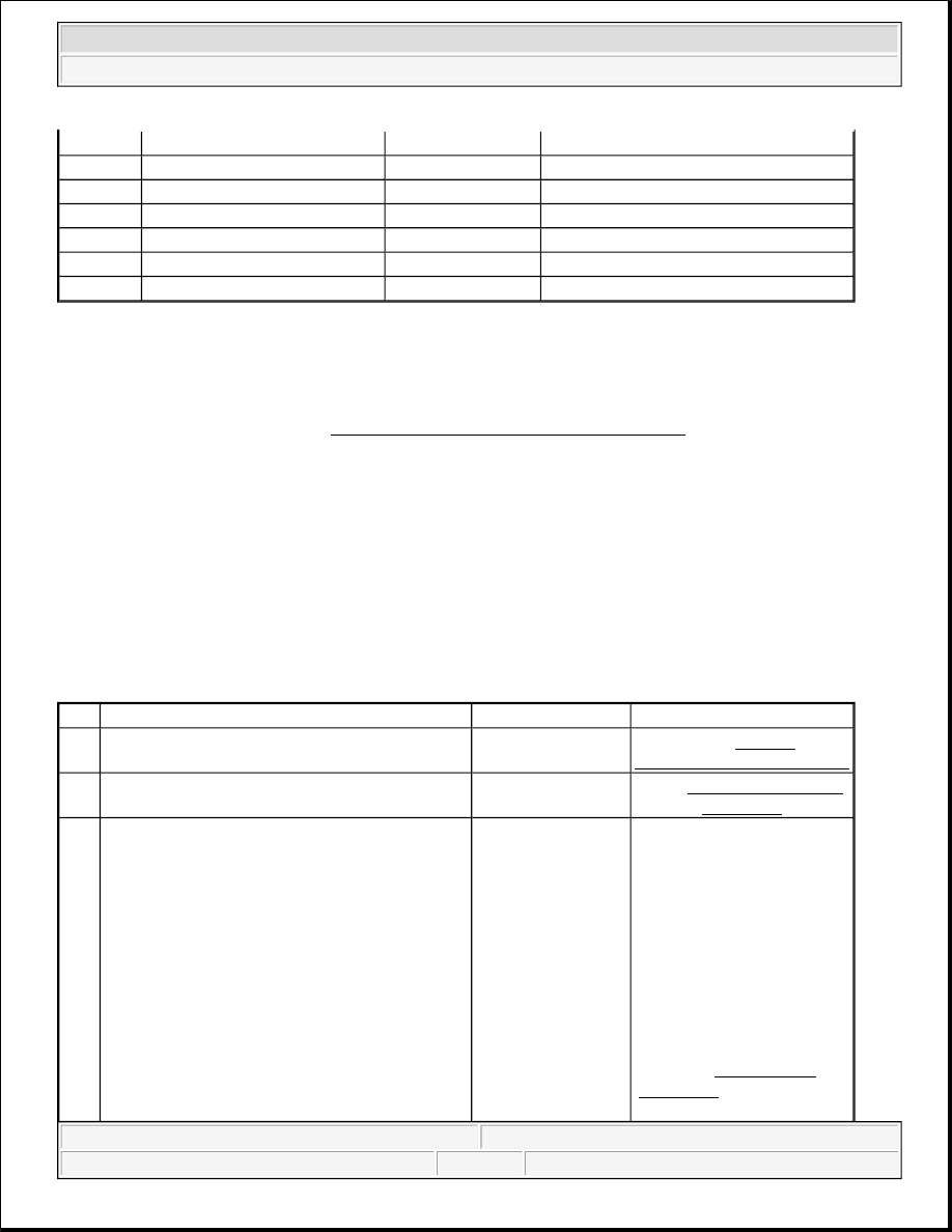
DIAGNOSTIC SYSTEM CHECK - ENGINE ELECTRICAL 

Diagnostic System Check - Engine Electrical 

A

BN

4

Accessory Voltage

B

RD/WH

342

Battery Positive Voltage

C

PK

3

Ignition 1 Voltage

D

YE

5

Crank Voltage

E

WH

1390

Acc/Run/Crank Voltage

F

RD

142

Battery Positive Voltage

G

OG

300

Ignition 3 Voltage

Step

Action

Yes

No

1

Did you perform the Battery Inspection/Test?

Go to Step 2

Go to Battery 

Inspection/Test (Non-HP2)

2

Install a scan tool. 
Does the scan tool power up?

Go to Step 4

Go to Scan Tool Does Not 

Power Up

3

1. Access the Class 2 Power Mode in the 

Diagnostic Circuit Check on the scan tool. 

2. Rotate the ignition switch through all 

positions while observing the ignition 
switch power mode parameter.  

Does the ignition switch parameter reading 
match the ignition switch position for all switch 
positions?

IMPORTANT:

The engine may start during the following 
step. Turn OFF the engine as soon as you 
have observed the Crank power mode.

Go to Step 4

Go to Power Mode 

Mismatch in Body Control 

System


2004 Hummer H2 

2004 ELECTRICAL Engine Electrical - Hummer H2


SCAN TOOL DATA LIST 

Powertrain Control Module (PCM) 

SCAN TOOL DATA DEFINITIONS 

4

1. Turn ON the ignition, with the engine 

OFF.  

2. Attempt to communicate with each 

module on the class 2 serial data circuit. 

If using a Tech 2, obtain this information 
using the Class 2 Message Monitor 
feature. 

Does the scan tool communicate with any 
module on the class 2 serial data circuit?

Go to Step 5

Go to Scan Tool Does Not 

Communicate with Class 2 

Device

5

1. Select the Display DTCs function for each 

module. 

If using a Tech 2, use the Class 2 DTC 
Check feature in order to determine which 
modules have DTCs set. 

2. Record all of the displayed DTCs the 

DTC status and the module which set the 
DTC.  

Does the scan tool display any DTCs?

Go to Step 6

Go to Symptoms - Engine 

Electrical

6

Does the scan tool display any DTC beginning 
with "U"?

Go to Diagnostic 

Trouble Code 

(DTC) List

Go to Step 7

7

Does the scan tool display any DTC beginning 
with "P"?

Go to Powertrain 

DTC list in Engine 

Controls

Go to Step 8

8

Does the scan tool display any DTC beginning 
with "B"?

Go to Diagnostic 

Trouble Code 

(DTC) List

Go to Diagnostic Trouble 

Code (DTC) List

Scan Tool Parameter

Data List

Units Displayed

Typical Data Value

Ignition ON/Engine OFF

Ignition 1 Signal

Engine 1,2 Data

Volts

9-14v

GEN L-Terminal Signal Command

Engine 2 Data

OK/No Output

OK

GEN F-Terminal Signal

Engine 2 Data

%

10-90%


2004 Hummer H2 

2004 ELECTRICAL Engine Electrical - Hummer H2


Ignition 1 Signal  

The scan tool displays the current voltage at the battery. 

GEN L-Terminal Signal Command  

The scan tool displays OK/No Output. The scan tool displays OK until malfunction is detected on the 
generator L terminal circuit, then it reads No Output. 

GEN F-Terminal Signal  

The scan tool displays 0%-100%. The scan tool displays 0%-5% until the engine is running, then the 
percentage value varies depending on electrical loads. 

DIAGNOSTIC TROUBLE CODE (DTC) LIST 

Diagnostic Trouble Code (DTC) List 

DTC B1327 

Circuit Description 

All vehicle modules monitor system voltage. The system voltage message is sent to other modules via Class 2 
message. When the system voltage drops below the specified range DTC B1327 shall set within the affected 
module. 

Conditions for Running the DTC 

This DTC shall run only if the module has power, ground and the ignition is not in START mode. This DTC 
shall execute regardless of the battery voltage, except when the DTC B1390 is set current. 

Conditions for Setting the DTC 

z

This DTC shall be set as current when the voltage falls below 9.0 volts for 1.2 seconds.  

z

When the vehicle exits START the module shall delay checking the voltage for 2 seconds.  

Action Taken When the DTC Sets 

DTC

Diagnostic Procedure

Modules

B1327

DTC B1327

BCM

B1328

DTC B1328

BCM

P0562

DTC P0562

PCM

P0563

DTC P0563

PCM

P1637

DTC P1637

PCM

P0622

DTC P0622

PCM

P0615

DTC P0615

PCM


2004 Hummer H2 

2004 ELECTRICAL Engine Electrical - Hummer H2


z

A message shall be sent out on the class 2 lines to notify all other modules of low battery voltage.  

z

The modules disable the setting of U codes and other DTCs.  

Conditions for Clearing the DTC 

z

The DTC will clear current status when the voltage is greater than 9.5 volts for 1.2 seconds.  

z

A history DTC will clear after 50 consecutive ignition cycles if the condition for the malfunction is no 
longer present.  

z

Use the ON-Board clearing DTCs feature.  

z

Use a scan tool.  

Test Description 

The numbers below refer to the step numbers on the diagnostic table. 

3: Tests for the proper voltage at battery positive voltage sense circuit of the module, if voltage is not 
within the proper operating range, the voltage sense circuit needs to be tested.  

4: Tests the circuit for high resistance.  

5: Tests for the proper ground circuit for the module.  

DTC B1327 

Step

Action

Value

(s)

Yes

No

Schematic Reference:Starting and Charging Schematics or Power Distribution Schematics in 
Wiring Systems 
Connector End View Reference:Master Electrical Component List in Wiring Systems

1

Did you perform the Engine Electrical Diagnostic System 
Check?

-

Go to 

Step 2

Go to Diagnostic 

System Check - 

Engine Electrical

2

1. Install a scan tool.  

2. Turn ON the ignition, with the engine OFF.  

3. With a scan tool, observe the battery voltage parameter 

in the affected module data list. Or with a DMM, 
measure the battery voltage at the appropriate circuit of 
the module.  

Does the voltage measure greater than the specified value?

9.4 V

Go to 

Step 6

Go to Step 3

3

1. Turn OFF the ignition.  

2. Disconnect the harness connector of the module setting 

the DTC B1327.  

3. Measure the voltage between the battery positive 

voltage circuit of the module setting the DTC B1327 
and the ground circuit of the module setting the DTC 

9.4 V


2004 Hummer H2 

2004 ELECTRICAL Engine Electrical - Hummer H2


Content   ..  1114  1115  1116  1117   ..