Hummer H2. Manual - part 1095


  Index      Hummer     Hummer H2 - service repair manual 2004 year


Search            


Content   ..  1093  1094  1095  1096   ..


Hummer H2. Manual - part 1095


3. Attach the end of one jumper cable to the positive terminal of the discharged battery.  

4. Attach the other end of the first cable to the positive terminal of the booster battery.  

5. Attach one end of the remaining jumper cable to the negative terminal of the booster battery. 

6. Make the final connection of the negative jumper cable to the block or suitable bracket connected directly 

to the block, away from the battery.  

7. Start the engine of the vehicle that is providing the jump start and turn off all electrical accessories. Raise 

the engine RPM to approximately 1,500 RPM.  

8. Crank the engine of the vehicle with the weak battery. 

If the engine does not crank or cranks too slowly, perform the following steps: 

1. Turn the ignition OFF.  

2. Allow the booster vehicle engine to run at approximately 1,500 RPM for 5 minutes.  

3. Attempt to start the engine of the vehicle with the discharged battery.  

9. Reverse the steps exactly when removing the jumper cables. The negative battery cable must first be 

disconnected from the engine that was jump started.  

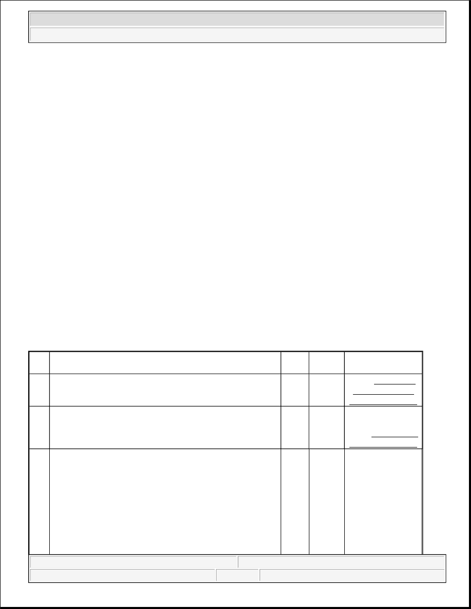
CHARGING SYSTEM TEST (CS/AD/SI GENERATORS) 

Charging System Test (CS/AD/SI Generators) 

NOTE:

Do not connect the negative charger lead to the housings of other vehicle 
electrical accessories or equipment. The action of the battery charger may 
damage such equipment.

Step

Action

Value

(s)

Yes

No

1

Did you perform the Engine Electrical Diagnostic System 
Check?

-

Go to 

Step 2

Go to Diagnostic 

System Check - 

Engine Electrical

2

Start the engine. Observe the charge indicator on the 
instrument cluster (IPC). 
Does the charge indicator illuminate or message center (DIC) 
display a charging system message?

-

Go to 

Step 3

Go to Symptoms - 

Engine Electrical

3

1. Turn OFF the ignition.  

2. Connect the red lead of the J 41450-B Universal CS 

Generator Test Harness to the generator output 
terminal.  

3. Connect the black lead of the J 41450-B to the metal 

IMPORTANT:

The green POWER lamp of the tester should remain 
illuminated while the tester is being used.

-


2004 Hummer H2 

2004 ELECTRICAL Engine Electrical - Hummer H2


generator housing.  

Does the green POWER lamp on the tester illuminate?

Go to 

Step 6

Go to Step 4

4

Measure the voltage from the output terminal of the 
generator to the generator metal housing. 
Does the voltage measure equal to the specified value?

12.0 V

Go to 

Step 14

Go to Step 5

5

Measure the voltage from the output terminal of the 
generator to the battery negative terminal. 
Does the voltage measure equal to the specified value?

12.0 V

Go to 

Step 12

Go to Step 11

6

1. Turn OFF completely the load tool before connecting 

or disconnecting a carbon pile load tester to the 
battery. Otherwise, sparking at the terminals could 
cause battery gasses to explode.  

2. Connect a carbon pile tester to the vehicle. 

3. Connect an inductive ammeter to the output circuit of 

the generator.  

4. Disconnect the generator harness connector.  

5. Locate the matching harness connector on the J 41450-

B , and connect the connector to the generator.  

Does the red DIAGNOSTIC lamp on the tester illuminate?

IMPORTANT:

Ensure that all generator output circuit wires pass 
through the inductive probe.

-

Go to 

Step 7

Go to Step 13

7

1. Start the engine and allow it to idle for 30 seconds.  

2. Increase the engine speed to 2,500 RPM.  

Does the red DIAGNOSTIC lamp on the tester illuminate?

-

Go to 

Step 15

Go to Step 8

8

1. Maintain the engine speed at 2,500 RPM. 

2. Turn ON the load of the carbon pile tester and increase 

the load until the generator output is equal to the Load 
Test value given in Generator Usage.  

Does the red DIAGNOSTIC lamp on the tester illuminate?

IMPORTANT:

If the generator is not capable of producing the 
Load Test amps, operate the generator at it's 
maximum possible output.

-

Go to 

Step 15

Go to Step 9

1. Maintain the engine speed at 2,500 RPM and continue 


2004 Hummer H2 

2004 ELECTRICAL Engine Electrical - Hummer H2


CHARGE INDICATOR ALWAYS ON 

9

to operate the generator at the load test value.  

2. Measure the voltage drop from the output terminal of 

the generator to the positive terminal on the battery. 
Refer to Circuit Testing and to Wiring Repairs in 
Wiring Systems.  

Does the voltage measure greater than the specified value?

0.5 V

Go to 

Step 11

Go to Step 10

10

1. Maintain the engine speed at 2,500 RPM and continue 

to operate the generator at the load test value.  

2. Measure the voltage drop from the battery negative 

terminal to the metal housing of the generator. Refer to 
Circuit Testing and to Wiring Repairs in Wiring 
Systems.  

Does the voltage measure greater than the specified value?

0.5 V

Go to 

Step 12

Go to Step 16

11

Repair the high resistance or an open in the output circuit of 
the generator. Refer to Circuit Testing and to Wiring 
Repairs
 in Wiring Systems. 
Did you complete the repair?

-

Go to 

Step 16

-

12

Repair the high resistance or open in the ground circuit of the 
generator. Refer to Circuit Testing and to Wiring Repairs 
in Wiring Systems. 
Did you complete the repair?

-

Go to 

Step 16

-

13

1. Disconnect the J 41450-B tester harness connector 

from the generator, but leave the alligator clips 
connected so that the green POWER lamp remains 
illuminated.  

2. Connect a jumper lead, with an in-line 100-ohm 

resistor between the J 41450-B tester harness 
connector terminal B of the generator and a good 
ground. Refer to Engine Electrical Connector End 
Views
 .  

Does the red DIAGNOSTIC lamp illuminate?

-

Go to 

Step 15

Go to Step 14

14

There is a problem with the J 41450-B . Refer to the 
manufacturers instructions, how to test the J 41450-B for 
proper operation. 
Has the J 41450-B tester been replaced?

-

Go to 

Step 3

-

15

Replace the generator. Refer to Generator Replacement . 
Did you complete the replacement?

-

Go to 

Step 16

-

16

Operate the vehicle in order to verify the repair. 
Did you correct the condition?

-

System 

OK

Go to Step 2


2004 Hummer H2 

2004 ELECTRICAL Engine Electrical - Hummer H2


Charge Indicator Always On 

CHARGE INDICATOR INOPERATIVE 

Charge Indicator Inoperative 

Step

Action

Yes

No

1

Did you perform the Diagnostic System Check for Starting 
and Charging?

Go to 

Step 2

Go to Diagnostic System 

Check - Engine Electrical

2

1. Turn ON the ignition, with the engine OFF.  

2. Observe the Charge indicator on the instrument 

cluster (IPC).  

Does the charge indicator illuminate?

Go to 

Step 3

Go to Symptoms - Engine 

Electrical

3

1. Turn OFF the ignition.  

2. Disconnect the generator connector.  

3. Turn ON the ignition, with the engine OFF.  

Does the charge indicator illuminate?

Go to 

Step 4

Go to Charging System 

Test (CS/AD/SI 

Generators)

4

Test the charge indicator control circuit for a short to 
ground. Refer to Circuit Testing and Wiring Repairs in 
Wiring Systems. 
Did you find and correct the condition?

Go to 

Step 6

Go to Step 5

5

Replace the PCM. Refer to Powertrain Control Module 
(PCM) Replacement
 in Engine Controls.Is the action 
complete?

IMPORTANT:

The replacement PCM must be programmed.

Go to 

Step 6

-

6

Operate the system in order to verify the repair. 
Did you correct the condition?

System 

OK

Go to Step 3

Step

Action

Yes

No

1

Did you perform the Diagnostic System 
Check for Starting and Charging?

Go to Step 2

Go to Diagnostic 

System Check - 

Engine Electrical

2

Turn ON the ignition, with the engine OFF.
Does the battery charge indicator illuminate 
during the bulb check?

Go to Testing for Intermittent 

Conditions and Poor 

Connections in Wiring 

Systems

Go to Step 3

3

Replace the charge indicator bulb. Refer to 
Instrument Panel Cluster (IPC) 
Replacement
 in Instrument Panel, Gauges 
and Console. 
Did you complete the replacement?

Go to Step 4

-


2004 Hummer H2 

2004 ELECTRICAL Engine Electrical - Hummer H2


Content   ..  1093  1094  1095  1096   ..