Hummer H1 (2006+). Manual - part 349
12-72
Electrical System
_______________________________________________________
3.
Pull the CTIS module out enough to gain access to the wiring harness and air lines that attach to the back of the module.
4.
Note the position of the two air lines on the back of the air pressure gauge and disconnect them. Tagging the lines prior to
removal to assure proper installation is recommended.
5.
Disconnect connector C12 from the instrument panel harness and remove the CTIS module.
Installation
1.
Connect connector C12 to the instrument panel harness.
2.
Install the air pressure lines to the back of the air pressure gauge. Make sure to install lines in the same position as they were
removed.
3.
Install the CTIS module in the instrument panel and secure with four allen screws.
CTIS Air Pressure Gauge Replacement
WARNING: The CTIS system components are subject to high air pressure. Always relieve the air pressure prior to
servicing the CTIS system. Failure to follow this warning may result in serious injury.
Removal
1.
Remove the center dash assembly bezel.
2.
Remove the two air lines at the quick disconnects.
3.
Remove the air pressure gauge back lighting bulb.
4.
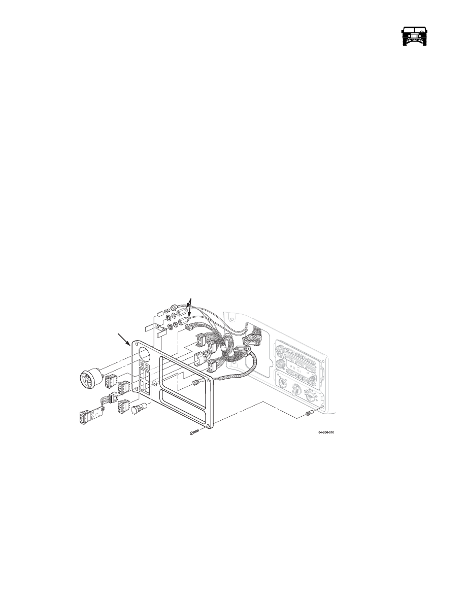
Remove the two retainer nuts that secure the air pressure gauge retainer bracket (Figure 12-55).
5.
Remove the air pressure gauge retainer bracket and the air pressure gauge from the bezel.
Figure 12-55: CTIS Module Break Down
Installation
1.
Install the air pressure gauge, retainer bracket and the nuts.
2.
Install the air pressure gauge back lighting bulb.
3.
Install the air lines and the bezel.
Inflate/Deflate and Tire Selector Switch Replacement.
WARNING: The CTIS system components are subject to high air pressure. Always relieve the air pressure prior to
servicing to the CTIS system. Failure to follow this warning may result in serious injury.
04-S06-010
QUICK
DISCONNECT
CENTER
DASH
BEZEL