Hummer H1 (2006+). Manual - part 327
 

  Index      Hummer     Hummer H1 DMAX - service repair manual 2006 year


Search            


Content   ..  325  326  327  328   ..


Hummer H1 (2006+). Manual - part 327


11-42 Heating/Ventilation/Air Conditioning (HVAC)

______________________

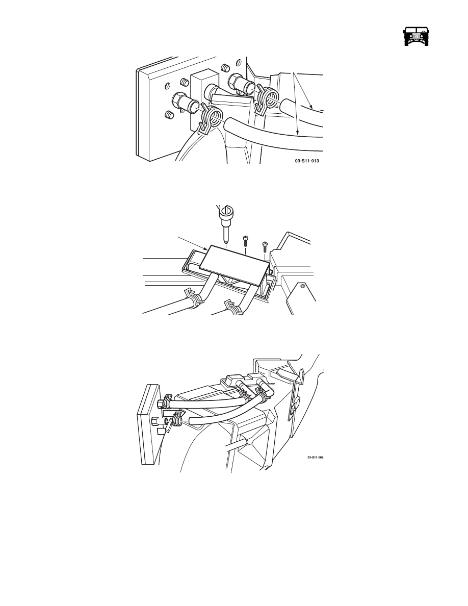
Figure 11-34:   Heater Core Tube Removal

5.

Carefully remove the hoses from the heater core.

6.

Remove the retaining plate (Figure  11-35).

Figure 11-35:   Retaining Bracket Removal

7.

Remove the heater core from the HVAC unit. Note positioning of any foam tape on the heater core and duplicate on the new
part (Figure  11-36).

Figure 11-36:   Removing Heater Core

Installation

1.

Apply new foam tape in same position as on the old heater core. 

2.

Install heater core into the HVAC unit.

3.

Install the retaining plate.

4.

Install the heater hoses and secure with the constant tension clamps.

5.

Install the protective cover.

6.

Install the HVAC unit in the vehicle.

HEATER CORE

EXTENSION TUBES

HEATER CORE 

RETAINING PLATE

03-S11-008

_____________________

 Heating/Ventilation/Air Conditioning (HVAC)  11-43

EVAPORATOR

Removal

NOTE: Observe the screws as they are removed to ensure correct screws are used in the correct location on the assembly.

1.

Remove the HVAC unit from the vehicle (Refer to “Main Unit Replacement” on page 11-37).

2.

Remove the heater core from the main unit (Refer to “Heater Core Removal” on page 11-41).

3.

Disconnect the vacuum harness from the vacuum motors. The motors are color coded to the vacuum tubing (Figure  11-37).

Figure 11-37:   Vacuum Door Motor Harness

4.

Remove the air intake housing from the main unit by removing the attaching screws at the blower housing (Figure  11-39) and
the bracket at the front of the unit (Figure  11-38).

Figure 11-38:   Air Intake Box Front Bracket Removal

Figure 11-39:   Lower Blower Housing Hardware Removal

VACUUM DOOR 

MOTOR HARNESS

7-S11-052

11-44 Heating/Ventilation/Air Conditioning (HVAC)

______________________

5.

Remove the floor door arm retaining push clip, arm and the two washers from the floor door (Figure  11-40).

Figure 11-40:   Push Clip Removal

6.

Remove the screws securing the vacuum motor mounting plate to the main HVAC unit and remove the mounting plate (Figure
 11-41).

7.

Remove the screws securing the case halves together. Do not attempt to separate the case at this time (Figure  11-41).

CAUTION: Do not attempt to pull the switch out of the case, the capillary tube is secured to the evaporator.

8.

Using a utility knife, carefully cut through the sealer between the two case halves. Use caution to prevent cutting the case.

Figure 11-41:   Case Half Hardware Removal

SCREW

THERMOSTATIC CYCLING SWITCH

S-CLIP

_____________________

 Heating/Ventilation/Air Conditioning (HVAC)  11-45

9.

Using a putty knife or scraper, carefully spread apart the entire case seam. 

10. Separate the case halves. Note that the thermostatic cycling switch must be separated from the evaporator.

11. Remove the permagum tape from around the liquid and the vapor tubes and discard.

12. Remove the expansion valve block from the passthrough plate, discard the gasket (Figure  11-42).

Figure 11-42:   Expansion Valve Removal

13. Remove the screws securing the passthrough plate support bracket to the main unit (Figure  11-43).

Figure 11-43:   Passthrough Plate Support Removal

14. Remove the bolt securing the passthrough plate to the evaporator manifold connection, remove the plate and the support

bracket.

15. Remove the evaporator from the unit (Figure  11-44).

16. Carefully remove the capillary tube from the evaporator, noting the positioning in the evaporator fins (Figure  11-44).

Figure 11-44:   Evaporator Removal

17. Disconnect the evaporator extension tubes at the O-ring fittings (Figure  11-45). Discard the O-rings.

EXPANSION VALVE

7-S11-044

7-S11-050

THERMOSTATIC

CYCLING SWITCH


Content   ..  325  326  327  328   ..