Hummer H1 (2006+). Manual - part 312
 

  Index      Hummer     Hummer H1 DMAX - service repair manual 2006 year


Search            


Content   ..  310  311  312  313   ..


Hummer H1 (2006+). Manual - part 312


10-110 Body

____________________________________________________________________

Disassembly

1.

Place the tailgate on a padded work surface and remove the hinge retainer rivets. Remove the hinge and clean any debris from 
the rivet holes.

2.

Clean the tailgate and apply a light coat of seam sealant to the hinge mounting area.

Assembly

1.

Transfer hole position with long scribe or use a paper template to mark hole location on new hinge. Drill holes with 3/16” drill
and deburr.

2.

Using three 0.187 in. x 0.626 in. rivets, fasten the hinge to the lower set of holes on the tailgate. 

3.

Fasten the hinge to the upper set of holes on the tailgate with the three 0.187 in. x 0.563 in. rivets.

Installation

1.

Position the tailgate on the bed and secure with the tailgate chains. Loosely install the bolts, washers and the locknuts into the 
hinges. Insert the proper amount of shims under each hinge.

2.

Slightly tighten the bolts, but not tight them enough to restrict movement into alignment with tape marks.

3.

Align the hinges and the tailgate into proper position and torque the bolts to 26 lb-ft (35 N•m). Remove any excess sealant
from the hinges and the body.

4.

Refinish the hinges and the fasteners as required.

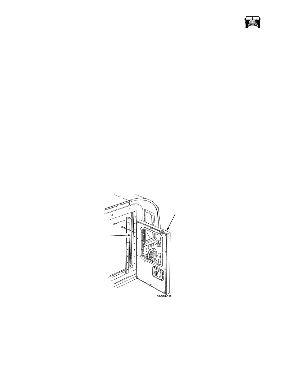
VERTICAL DOOR REPLACEMENT

Removal

1.

Remove the seven screws securing the hinge to the door.

2.

Slowly pull the door away from the hinge to expose the interior lock harness connections.

3.

Disconnect the interior door lock harness from the contacts on the hinge and tape to the door to prevent loss.

Figure 10-134:   Rear Vertical Door Replacement

Installation

1.

Position the door close to the hinge to allow the interior door lock harness to be connected to the contacts on the hinge.

2.

Secure the hinge to the door frame with the seven screws (Figure  10-134). 

3.

Verify the operation of the door locks and the door latch.

4.

If alignment is necessary, loosen the seven screws on the interior side of the door hinge. The slots in the hinge will allow up
and down adjustment.

REAR

VERTICAL

DOOR

DOOR

FRAME

___________________________________________________________________

 Body  10-111

5.

Tighten the seven screws in the hinge.

Window Replacement

Removal

Remove the eleven screws, window retainer bracket and the window from the rear vertical door (Figure  10-135). 

Figure 10-135:   Window Replacement

Installation

Secure the window to the rear vertical door with the window retainer bracket and the eleven screws (Figure  10-135). 

Door Handle Replacement

Removal

1.

Remove the rear door window. 

2.

Remove the four screws and the interior door handle from the door (Figure  10-136).

3.

Remove the twelve screws and the close-out panel from the door.

4.

Remove the two cotter pins, washers and the latch rods from the exterior door handle.

5.

Remove the lock motor rod from the door handle (Figure  10-138).

6.

Remove the four spacers and the exterior door handle from the door. 

WINDOW

WINDOW

REAR

VERTICAL

DOOR

 RETAINER

BRACKET

10-112 Body

____________________________________________________________________

Figure 10-136:   Door Handle Replacement

Installation

1.

Secure the exterior door handle to the door with the four spacers (Figure  10-136). 

2.

Install the lock motor rod to the door handle lock latch with the plastic clip (Figure  10-138).

3.

Secure the latch rods to the exterior door handle with the two washers and the cotter pins. 

4.

Secure the close-out panel to the door with the twelve screws.

5.

Secure the interior door handle to the door with the four screws. 

6.

Install the rear door window. 

Door Latch and Latch Rod Replacement

Removal

1.

Remove the rear door window. 

2.

Remove the four screws and the interior door handle from the door (Figure  10-137). 

3.

Remove the twelve screws and the close-out panel from the door. 

4.

Remove the pin connector, cotter pin, washer and the latch rod from the exterior door handle.

5.

Remove the lock motor rod from the door handle (Figure  10-138).

6.

Remove the four screws and the lower door latch bracket from the door.

7.

Remove the cotter pin and the latch rod from the lower door latch.

8.

Remove the four screws and the locknuts holding the lower door latch to the lower door latch bracket (Figure  10-137).

INTERIOR

DOOR

HANDLE

COTTER

PINS

EXTERIOR

DOOR

HANDLE

LATCH

RODS

CLOSE-OUT

PANEL

SPACER

___________________________________________________________________

 Body  10-113

Figure 10-137:   Door Latch and Latch Rod Replacement

Installation

1.

Secure the lower door latch to the lower door latch bracket with the four screws and the locknuts (Figure  10-137). 

2.

Secure the latch rod to the lower door latch with the cotter pin. 

3.

Secure the lower door latch bracket to the door with the four screws.

4.

Secure the latch rod to the exterior door handle with the pin connector, washer and the cotter pin (Figure  10-137). 

5.

Install the lock motor rod to the door handle lock latch with the plastic clip (Figure  10-138).

6.

Secure the close-out panel to the door with the twelve screws.

7.

Install the rear door window. Secure the interior door handle to the door with the four screws. 

LOWER DOOR LATCH

LATCH

ROD

LATCH

BRACKET

PIN CONNECTOR


Content   ..  310  311  312  313   ..