Hummer H1 (2006+). Manual - part 307
 

  Index      Hummer     Hummer H1 DMAX - service repair manual 2006 year


Search            


Content   ..  305  306  307  308   ..


Hummer H1 (2006+). Manual - part 307


10-90 Body

______________________________________________________________________

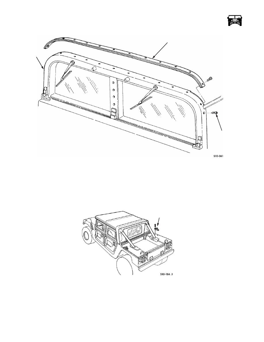
Figure 10-105:   A-Pillar Former Assembly Replacement

REAR SUPPORT BOW BRACKET REPLACEMENT

Removal

1.

Remove the rear support bow assembly.

2.

Remove the two screws and the support bow bracket from the body (Figure  10-106).

Figure 10-106:   Rear Support Bow Bracket Replacement

Installation

1.

Secure the bracket to the body with the two screws (Figure  10-106).

2.

Install the rear support bow assembly.

A-PILLAR

FORMER

A-PILLAR

WELLNUT

REAR

SUPPORT BOW

BRACKET

_____________________________________________________________________

 Body  10-91

FRONT STRIKER REPLACEMENT

Removal

Remove the locknut, washer, striker guard and the striker from the front door pillar (Figure  10-107).

Installation

Secure the striker and the striker guard to the front door pillar with the washer and the locknut (Figure  10-107). Tighten the lock-
nut to 41 lb-ft (56 N•m).

Figure 10-107:   Front Striker Assembly Replacement

REAR STRIKER ASSEMBLY REPLACEMENT

Removal

Remove the two screws, washers, backing plate and the rear striker assembly from the rear door pillar (Figure  10-108).

Installation

Secure the rear striker assembly to the rear door pillar with the backing plate, two washers and the screws (Figure  10-108). Tighten
the screws to 12 lb-ft (16 N•m).

Figure 10-108:   Rear Striker Assembly Replacement

FRONT

DOOR

PILLAR

STRIKER

STRIKER

GUARD

WASHER

LOCKNUT

REAR DOOR PILLAR

REAR

STRIKER

ASSEMBLY

BACKING

PLATE 

10-92 Body

______________________________________________________________________

BODY MOUNT REPLACEMENT

Removal

NOTE: Removal and installation procedures for intermediate and rear body mounts are the same. This procedure covers the left
intermediate body mount. 

1.

Remove the locknut, washer, bolt, washer and the spacer securing the sleeve, upper cushion and the lower cushion to the body 
bracket and the frame bracket (Figure  10-110).

2.

Raise the vehicle at the body reinforcement adjacent to the body mount to be removed (Figure  10-109).

3.

Raise the body far enough to separate the upper cushion from lower cushion and remove the sleeve, upper cushion and the
lower cushion (Figure  10-110).

Figure 10-109:   Left Side Body Mount Locations

Figure 10-110:   Body Mount Cushions Replacement

Installation

1.

Position the lower cushion, upper cushion and the sleeve between the body bracket and the frame bracket (Figure  10-110).

FRONT MOUNT

INTERMEDIATE

REAR MOUNT

MOUNT

BODY BRACKET

SLEEVE

UPPER

FRAME BRACKET

SPACER

LOWER

CUSHION

CUSHION

WASHER

BOLT

WASHER

LOCKNUT

_____________________________________________________________________

 Body  10-93

2.

Lower the body and ensure the lower cushion, sleeve, upper cushion and the body bracket align. Secure with the spacer,
washer, bolt, washer and the locknut. Tighten the locknut to 90 lb-ft (122 N•m).

ROCKER PANEL PROTECTION REPLACEMENT

Removal

NOTE: Removal of the rocker panel protection is similar for both sides. This procedure covers one side only.

NOTE: Socket head screws are secured in place with Loctite 242 and may require considerable effort to break loose.

1.

Remove the nine socket head screws securing the rocker panel protection to the body. Support the rocker panel protection with
a floor jack (Figure  10-111).

Figure 10-111:   Rocker Panel Protection 

3.

Remove the three nuts and washers securing rocker panel protection to front footwell. 

4.

Remove the three nuts and washers securing the rocker panel protection to the rear footwell.

CAUTION: Rocker panel protection is heavy. Remove with a floor jack.

5.

Remove the rocker panel protection from the body.

6.

Inspect the three retainer nuts on the body. Discard if damaged.

Installation

CAUTION: Rocker panel protection is heavy. Raise into place with a floor jack.

1.

Raise the rocker panel protection to the body. 

2.

Secure the rocker panel protection to the rear footwell with the three washers and the nuts. Do not tighten the nuts. 

3.

Secure the rocker panel protection to the front footwell with the three washers and the nuts. Tighten the nuts at the front and rear
footwells to 37 lb-ft (50 N•m). 

NOTE: Apply Loctite 242 to threads of socket head screws.

4.

Remove the floor jack and secure the rocker panel protection to the body with the nine socket head screws. Tighten the socket
head screws to 37 lb-ft (50 N•m).

GASKET

BODY

ROCKER PANEL

PROTECTION

SOCKET HEAD

SCREW


Content   ..  305  306  307  308   ..