Hummer H1 (2006+). Manual - part 267
 

  Index      Hummer     Hummer H1 DMAX - service repair manual 2006 year


Search            


Content   ..  265  266  267  268   ..


Hummer H1 (2006+). Manual - part 267


9-46 Axles, Suspension and Frame

__________________________________________

Figure 9-75:   Geared Hub Shim Gasket Location

5.

Remove the remaining bolts, washers, speed sensor bracket, drive gear retainer and the shim gasket(s) from the geared hub.

6.

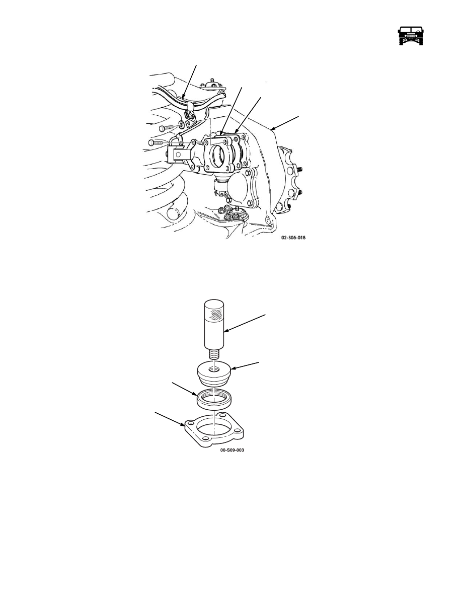
Secure the drive gear retainer in a vise with inserts and remove the input seal. Discard the input seal (Figure  9-76).

Figure 9-76:   Input Seal Installation

Installation

1.

Using driver handle J–8092 and input seal installer DT-47845, install the input seal in the drive gear retainer. Place the new
primary seal on the installer with the open side of the seal facing toward the drive gear retainer. Drive the seal in until the
installer bottoms against the drive gear retainer. The seal will be recessed in the drive gear retainer approximately 0.200". This
dimension is critical and must be achieved using the special tool (Figure  9-76).

2.

Secure the shim gasket(s) and the drive gear retainer to the geared hub with the washers and the bolts (Figure  9-75).

3.

Secure the vent line bracket and the speed sensor bracket to the drive gear retainer with the washers and the bolts. Tighten all
four bolts to 38 lb-ft. (52 N•m).

4.

Coat the lip of the input seal with gear oil (Figure  9-76).

VENT LINE BRACKET

DRIVE GEAR 

RETAINER

GEARED

 HUB

SHIM GASKET

DRIVER HANDLE

INPUT SEAL

INSTALLER

INPUT SEAL

DRIVE GEAR

RETAINER

J–8092

DT-47845

_________________________________________

 Axles, Suspension and Frame  9-47

5.

Stretch the v-seal over the seal area of the halfshaft with the thick side against the c-v joint  (Figure  9-77). Lubricate the thin
side of the v-seal with an all purpose grease. This portion of the v-seal will contact the stainless steel portion of the primary
seal when the halfshaft is installed.

Figure 9-77:   V-Seal Replacement

NOTE: Be sure that the bolt and the bolt hole are cleaned of old Loctite.

6.

Apply thread-locking compound to the halfshaft retaining bolt and secure the halfshaft to the geared hub with the lockwasher
and the halfshaft retaining bolt. Tighten the halfshaft retaining bolt to 37 lb-ft. (50 N•m) (Figure  9-78).

7.

Secure the washer and the access plug onto the geared hub. Tighten the access plug to 8-13 lb-ft. (11-18 N•m).

8.

Install the wheel.

Figure 9-78:   Halfshaft and Geared Hub

Geared Hub Repair

Disassembly

1.

Remove the geared hub.

2.

Position the geared hub with the spindle supporting the geared hub (Figure  9-79).

Figure 9-79:   Geared Hub Disassembly

V-SEAL

IN PLACE

THICK

THIN

C-V

JOINT

ROTOR

HALFSHAFT

GEARED

HALFSHAFT

ACCESS

PLUG

HUB

 RETAINING

 BOLT

SIDE COVER

GEARED HUB

SPINDLE

9-48 Axles, Suspension and Frame

__________________________________________

3.

Remove the eight bolts, washers and the side cover from the geared hub.

CAUTION:  If backlash between the drive and the driven gears is more than 0.018 in. (0.46 mm), both gears must be replaced.

4.

Mount the dial indicator J–8001 on the geared hub and index the indicator to register from one drive gear tooth. Move drive
gear back and forth while holding the driven gear stationary to read the backlash (Figure  9-80).

Figure 9-80:   Dial Indicator Positioning

5.

Remove the four bolts, washers and the steering arm cover from the geared hub (Figure  9-81).

6.

Remove the clamp nut lock screw from the clamp nut.

7.

Using the clamp nut socket J-42545, remove the clamp nut and keyed washer from the spindle.

NOTE: It may be necessary to lightly tap the threaded end of the spindle to release it from the inner spindle bearing.

8.

Lift the geared hub off the spindle.

9.

Remove the inner bearing, bearing spacer and the driven gear from the geared hub.

10. Remove the outer bearing spacer from the spindle.

11. Remove the four bolts, washers, drive gear retainer, shim gasket, inboard bearing cup and the drive gear from the geared hub

(Figure  9-82).

12. Remove the retaining washer from the inside drive gear or the geared hub.

13. Remove the spindle seal from the geared hub. Discard the seal.

14. Remove the input seal from the drive gear retainer. Discard the seal (Figure  9-83).

DRIVE

DIAL

GEARED HUB

INDICATOR

 GEAR

J–8001

_________________________________________

 Axles, Suspension and Frame  9-49

Figure 9-81:   Geared Hub Breakdown

Figure 9-82:   Drive Gear Removal

STEERING ARM COVER

CLAMP NUT

CLAMP NUT

LOCK SCREW

KEYED

INNER

BEARING

GEARED HUB

OUTER

 BEARING

 SPACER

SPINDLE

DRIVEN GEAR

 SPACER

 BEARING

 WASHER

   SOCKET

CLAMP NUT

DRIVE GEAR RETAINER

SHIM GASKET

INBOARD

BEARING CUP

DRIVE GEAR

RETAINING

GEARED HUB

SPINDLE SEAL

 WASHER


Content   ..  265  266  267  268   ..