Hummer H1 (2006+). Manual - part 266
9-42 Axles, Suspension and Frame
__________________________________________
3.
Install the drain plug in the geared hub.
4.
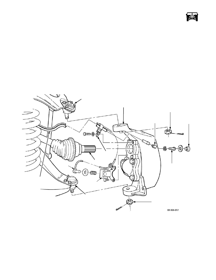
Remove the bolt, washer and the vent line/speed sensor lead bracket from the geared hub (Figure 9-70).
5.
Disconnect the vent line from the geared hub fitting.
6.
Remove the speed sensor from the sensor bracket on the geared hub.
7.
Remove the cotter pin, slotted nut and the washer from the tie rod end (Figure 9-69).
8.
Using puller J–24319–B, disconnect the tie rod end from the geared hub.
9.
Remove the access plug, washer, halfshaft retaining bolt, lockwasher and the halfshaft from the geared hub (Figure 9-70).
WARNING: Geared hub must be supported during removal and installation. Failure to support the geared hub may
cause personal injury or damage to the equipment.
10. Remove the cotter pin and the slotted nut from the upper ball joint. Remove the ball joint stud from the geared hub.
11. Remove the cotter pin and the slotted nut from the lower ball joint. Remove the ball joint stud from the geared hub.
12. Lower the support and remove the geared hub.
I
Figure 9-70: Geared Hub Replacement
Installation
WARNING: To avoid injury and damage to the equipment, support the geared hub during removal and installa-
tion.
1.
Position the geared hub between the upper and the lower control arms and secure the upper ball joint to the geared hub with the
slotted nut, but do not tighten (Figure 9-70).
2.
Secure the lower ball joint to the geared hub with the slotted nut, but do not tighten.
UPPER BALL JOINT
GEARED HUB
SLOTTED NUT
GEARED HUB
ACCESS
HALFSHAFT
RETAINING
BOLT
SLOTTED NUT
VENT LINE
VENT LINE
FITTING
PLUG
LOWER
BALL JOINT
BRACKET
HALFSHAFT
SPEED
SENSOR
SENSOR
BRACKET