Hummer H1 (2006+). Manual - part 262
9-26 Axles, Suspension and Frame
__________________________________________
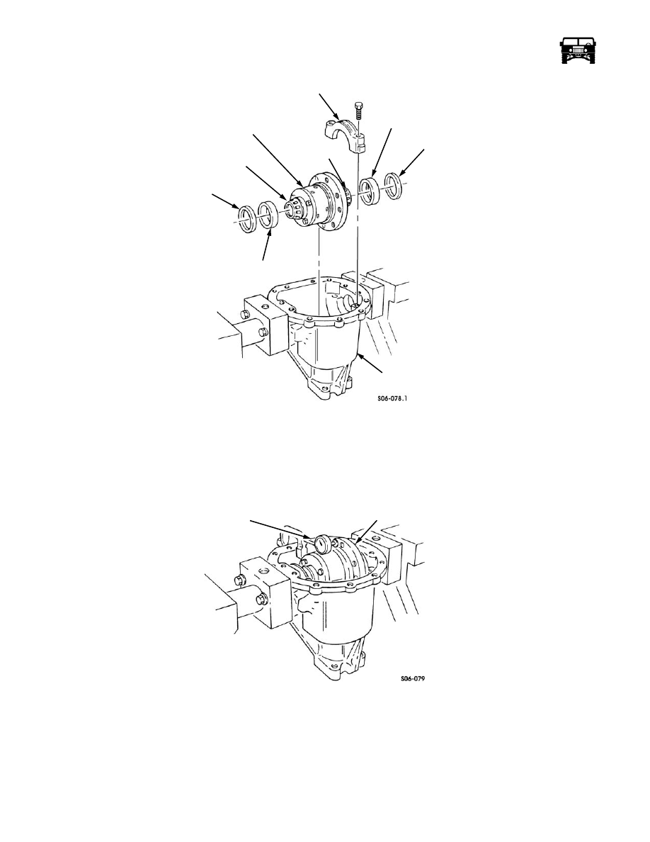
Figure 9-44: Side Bearing Cup and Shim Installation
33. Install the differential assembly, bearing cups and the shims in the housing.
34. Install the two bearing caps and the four bolts in the housing. Snug the bolts.
35. Mount the dial indicator on the housing and position the indicator to read off the ring gear mounting surface of the differential
assembly (Figure 9-45).
Figure 9-45: Dial Indicator Positioning For Case Runout Check
36. Pry between the differential assembly and the bearing cap on one side of the indicator. Pry on the opposite side to read the end
play.
BEARING CAP
BEARING
HOUSING
BEARING
SHIM
SIDE
DIFFERENTIAL
ASSEMBLY
SIDE
CUP
SHIM
BEARING
BEARING
CUP
RING GEAR
FLANGE OF CASE
DIAL INDICATOR